
One of the common objectives of electromagnetics simulation is to extract lumped quantities that can be used in electric circuit simulations. Keep reading to get step-by-step instructions on how to perform such a task using the COMSOL Multiphysics® software…
Editor’s note: This blog post was updated on January 11, 2023, to reflect updated modeling functionality.
Extracting Lumped Quantities in COMSOL®
You can easily extract lumped quantities for electric circuit simulations in COMSOL® with the following features and functionality:
- Automated extraction of resistance R, inductance L, and capacitance C using the Stationary Source Sweep and Frequency Domain Source Sweep study steps
- Predefined variables for storing the extracted lumped R, L, and C matrices — including automated evaluation and display in postprocessing
- The Electrical Circuit interface, with its support for automated import and export of circuits as SPICE .cir files
Here, we will focus on the new Circuit Extractor add-in, available for all licenses that offer the AC/DC Module. The Circuit Extractor is automatically installed if you have the default preferences set, but you can manually access it by following the instructions linked at the bottom of this blog post.
Introducing the Circuit Extractor Add-in
The Circuit Extractor add-in offers an easy way to directly convert the results of electromagnetics simulations into an Electrical Circuit physics interface and subsequently into a SPICE file. The supported physics interfaces for performing such an extraction are:
- Electric Currents for resistances
- Electrostatics and Electrostatics Boundary Elements for capacitances
- Magnetic Fields, Currents Only and Magnetic and Electric Fields for resistances, inductances, or impedances
Multiple physics interfaces and solutions can contribute to the same extracted circuit.
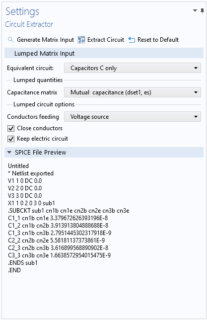
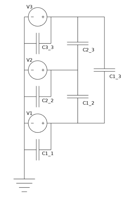
In order to use the Circuit Extractor add-in, a Stationary Source Sweep or a Frequency Domain Source Sweep must be solved for the physics of interest. Matrices that are generated when solving such studies are then used for generating the equivalent circuit. After solving, in the user interface of the Circuit Extractor add-in, you select the type of Equivalent Circuit and the Evaluation Group corresponding to the desired solution, and press the Extract Circuit button. This will open a window for saving the extracted SPICE file. Below, an example of the Circuit Extractor add-in user interface is shown on the left, along with a diagram of the corresponding circuit on the right.
At left: The Settings window for the Circuit Extractor UI after having extracted the equivalent capacitance of a three-terminals electrostatics model. At right: A diagram of the extracted circuit.
To locate and start using the Circuit Extractor add-in, follow these three steps:
- Open a blank model in COMSOL®
- Click the Developer tab in the ribbon and select Add-in Libraries
- Expand the AC/DC Module section and select the circuit_extractor check box (as shown in the image below)
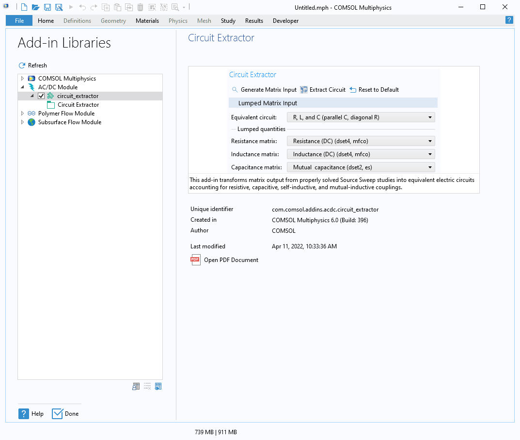
The COMSOL Multiphysics Add-in Libraries window showing the position of the Circuit Extractor.
You are now ready to use the Circuit Extractor add-in on any model without having to repeat this operation.
Getting Started with the Circuit Extractor
In the video below, you will see the Circuit Extractor in action:
After clicking the Extract Circuit button, a few different things happen:
- You are asked where you want to save the output
.cirfile - The text that was saved to the
.cirfile is added to the SPICE File Preview section - A second component of the model is created, which stores the extracted Electrical Circuit physics
All three of these actions generate the same circuit representation (shown below):
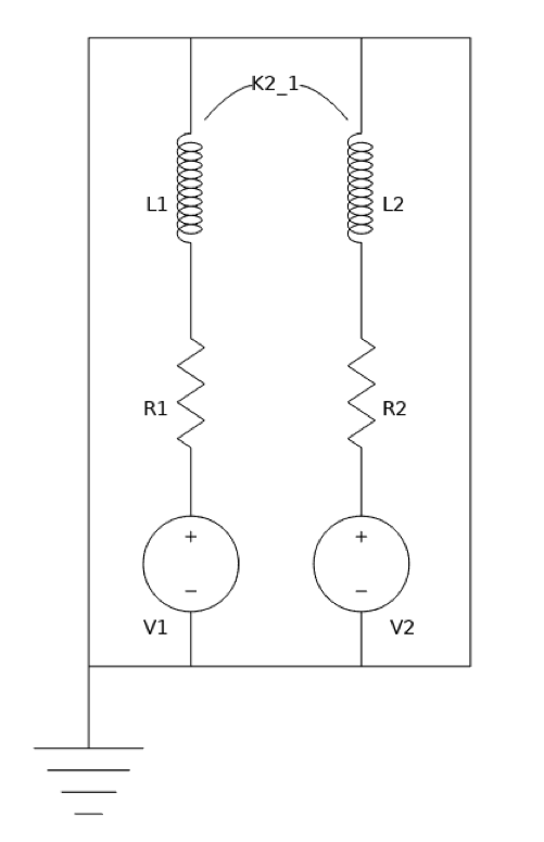
A diagram of the extracted circuit.
What Else Is Possible with the Circuit Extractor Add-In?
Before looking at more examples, we will first give additional insight into the add-in, including how a circuit is extracted and what options are available for further customization. The Circuit Extractor interface offers a few options for modifying your circuit, such as the option to choose the feeding element type. You can also decide not to close the conductors in case other circuital elements need to be added manually.
We have seen that a Stationary Source Sweep or a Frequency Domain Source Sweep study needs to be solved before running the Circuit Extractor add-in. When solving for one of these studies, the lumped matrices of the model are computed. Their common size is determined by the number of terminals that are defined at the physics level. Each nonzero element of these matrices corresponds to an element in the subcircuit. Here, the order of the rows and columns in the matrix is the same as the numbering of the feeding elements in the original physics interface. This numbering will then also be used in the extracted circuit.
The add-in scans the matrices inside an Evaluation Group. This output is the default for the Magnetic Fields Currents Only physics interface. So, what happens if the default output matrices have not been requested, have been deleted, or have been created in a format that is not compatible for SPICE transformation? For these cases, the add-in offers the Generate Matrix Input button. This button generates all possible lumped matrices from the existing solutions. They are output to the Evaluation Group feature under Results and can be used as Lumped quantities in the Add-in Lumped Matrix section.
You can use the drop-down menu(s) under Lumped quantities to select which matrices from the study results should be used for the circuit extraction. Depending on which equivalent circuit analogy is chosen, different options become available. The options for Equivalent Circuit are:
- Resistors R only
- Inductors L only
- Capacitors C only
- R and L (series, diagonal R)
- R and C (parallel, diagonal R)
- R, L, and C (parallel C, diagonal R)
- Impedances Z
We have now seen the add-in in use and learned what options there are for customizing your circuit model. Next, we will look at a case that focuses on verifying a model by comparing its results to a benchmark solution.
Case 1: RL Square Wave Response Verification
Let’s use the same model from the previous section but consider that the:
- Voltage source V1 is fed with a square signal: 1 mV peak, 50% duty cycle, 1 kHz frequency (shown in the plot below)
- Voltage source V2 is kept at zero, which corresponds to a short-circuited coil
You can perform a full finite element method (FEM) transient analysis to verify that when under these assumptions, the model produces the same result as the extracted electrical circuit. It’s best to run this analysis in a time-dependent simulation where the Magnetic Fields physics interface is solved for. (The model settings for this simulation are identical to those used in the E-Core Transformer tutorial model.)
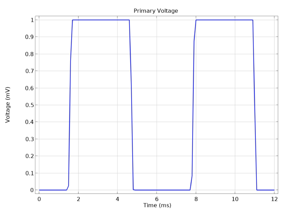
The voltage signal applied to the lower of the two coils, analyzed in the introductory case and case 1 models.
When a square signal is applied to the primary coil, the self-inductance RL response is expected to smoothen the resulting primary current. Furthermore, mutual inductive effects will generate currents on the secondary coil.
The plot below compares two approaches:
- A full FEM transient approach, solved with the Magnetic Fields interface
- A lumped approach, solved with the Electrical Circuit interface, which was extracted by the add-in
Despite the fact that the first approach is solving for about 30,000 degrees of freedom (DOFs), and the second one for only 4, the two agree almost perfectly.
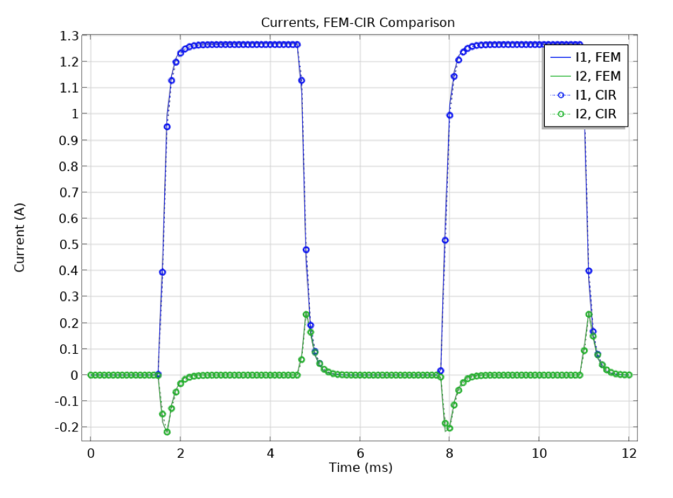
The resulting current in both coils. Comparison of FEM (solid lines) and extracted circuit simulation (markers and dotted lines).
You can inspect this model by downloading the file CircuitExtractor_blog_case1_RL_SquareWaveResponseVerification.mph from the Application Gallery.
Case 2: Resistors Network Stationary Current Verification
Let’s now consider a stationary study that is solving for a network of resistors, where the geometry is taken from the Importing and Meshing a PCB Geometry from an ODB++® Archive tutorial model. (Learn more about this geometry in the blog post “How to Import an ECAD Geometry for Printed Circuit Board Design”.)
An Electric Currents study is preformed, feeding the largest metal plate (highlighted in the image below). Six sources are applied — a combination of voltage and current sources — and a ground is set as well.
The lower-right corner of the image below shows the extracted resistance matrix.
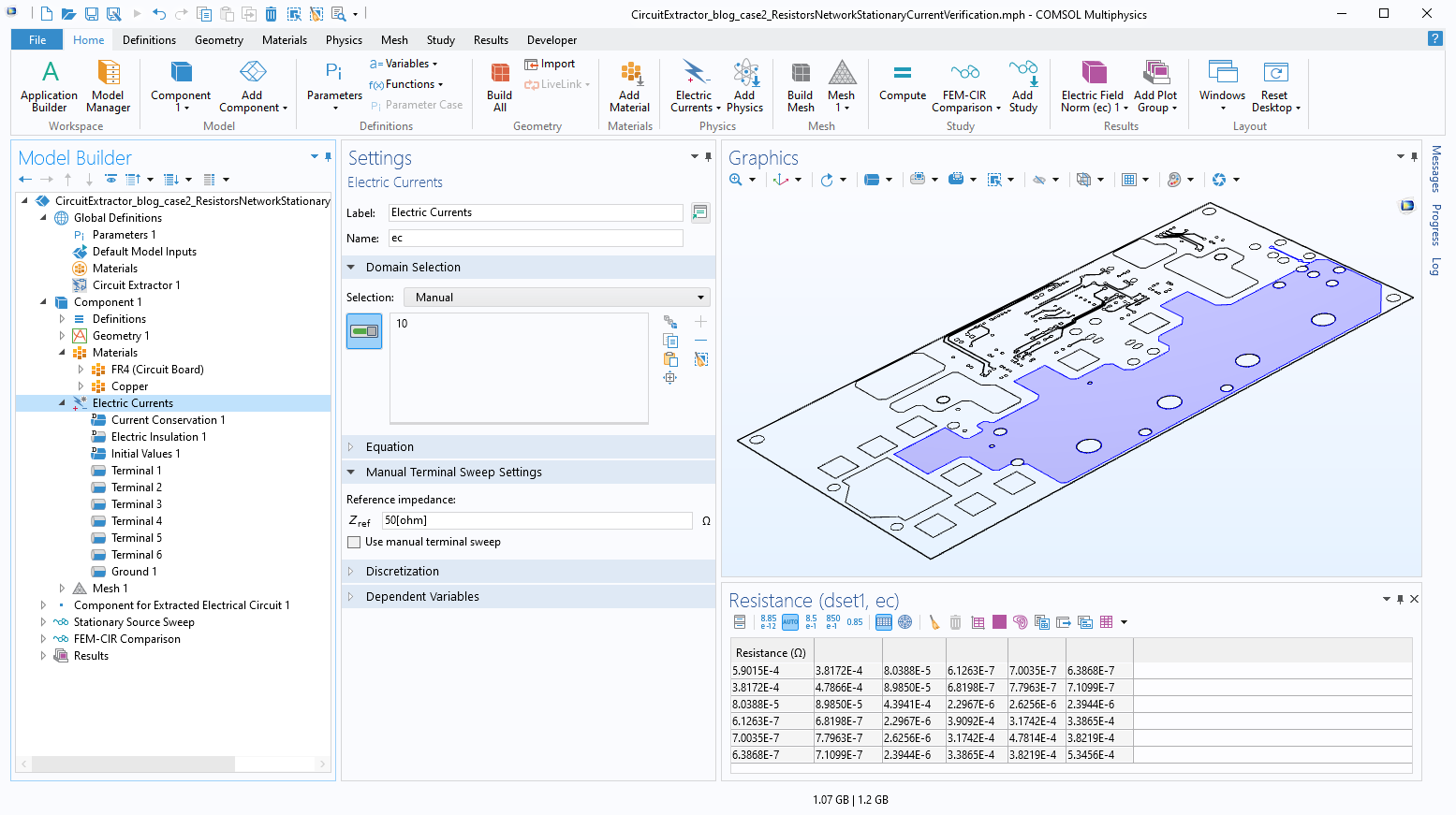
A planar circuit board (PCB) model in the Graphics window that highlights the metallic layer where an electric currents simulation is performed to extract the equivalent resistance network. The table on the lower-right of the UI shows the resulting resistance matrix.
Below, you can see the result and the exact comparison of the full FEM approach and the extracted circuit solution. You can inspect this model by downloading the file CircuitExtractor_blog_case2_ResistorsNetworkStationaryCurrentVerification.mph from the Application Gallery.
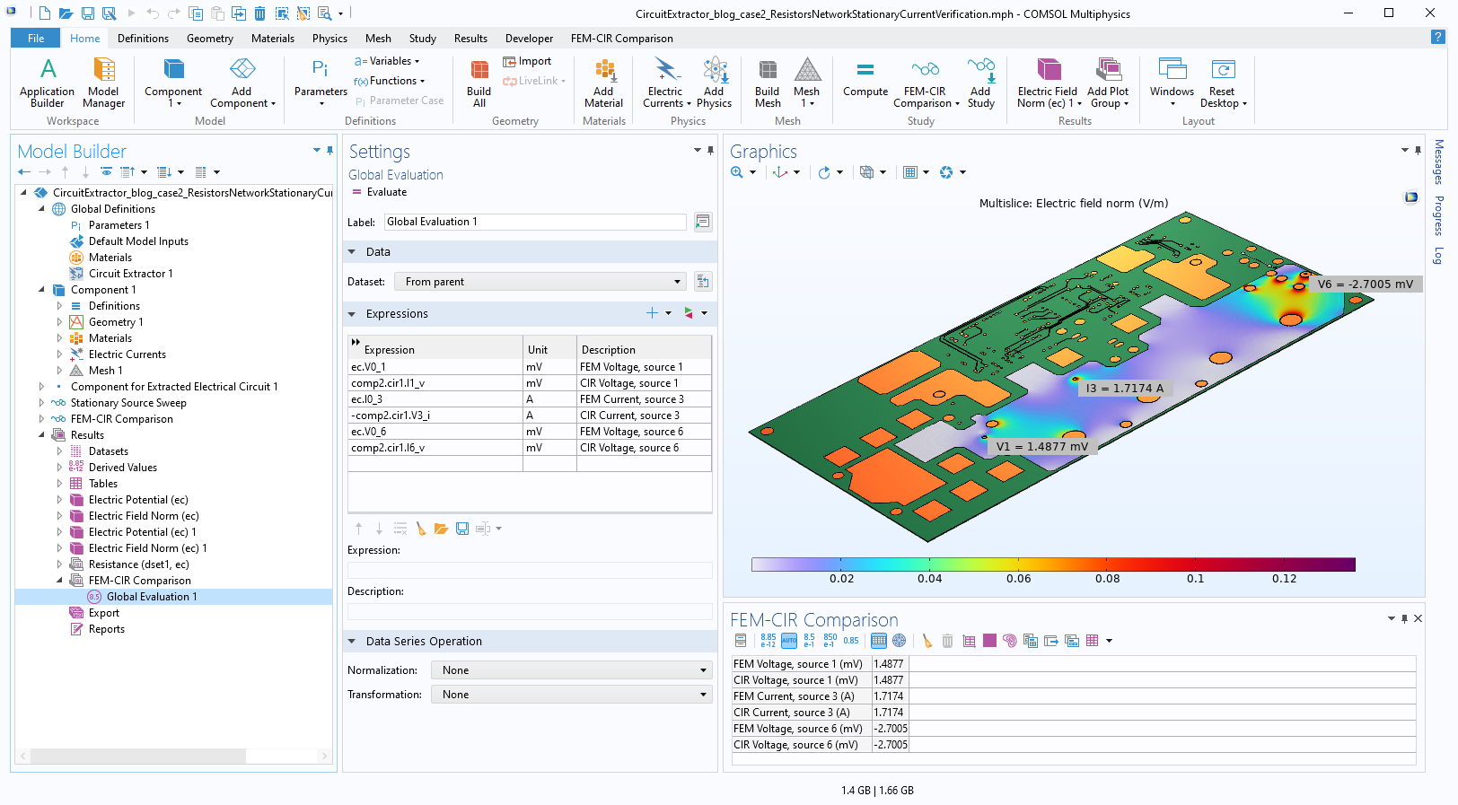
Results from the finite elements full fidelity model compared to those from the extracted electric circuit.
Case 3: RLC Frequency-Domain Extraction for PCB Coil Model
In the abovementioned cases, we analyzed examples where lumped parameters were extracted for one single physics only, and used in transient or stationary studies. Furthermore, we have limited ourselves to cases where a full FEM approach could easily be performed. In the final example, we mix lumped information from different physics, and use the extracted circuit to accomplish something that would be very difficult to do with a full finite element model. An especially challenging case involves an efficient frequency sweep from an inductive regime, all the way into a capacitive regime, for a model like the one featured in the Inductance Matrix Calculation of PCB Coils example. Here, we use this example and add an Electrostatic calculation to it for computing the capacitance matrix (as highlighted below).
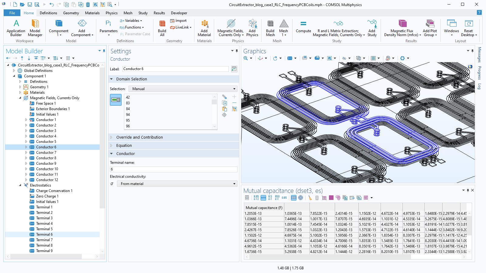
The geometry of the simulated 12 PCB coils along with the extracted capacitance matrix. The original tutorial model shows how to extract the R and L matrices in both the static domain and frequency domain.
The original model in the Application Gallery contains a first study that solves for Magnetic Fields, Currents Only and returns the resistance matrix R and the inductance matrix L, accounting for the inductive coupling between the 12 coils. In the modified version discussed here, a second study is available. This study solves for Electrostatics and returns the capacitance matrix C, accounting for the capacitive coupling between the same 12 coils.
The use of the Circuit Extractor remains the same with respect to the previous cases, but now the circuit can predict resonant behavior due to the RLC nature of the couplings between the conductors.
With the lumped approach, scanning the frequency response of the PCB coils from the static regime to the gigahertz regime is almost instantaneous: It only takes 30 seconds to compute the RL matrixes and 10 seconds to compute the C matrix. Some of the external circuital elements can be manually edited to better represent a physical connection. In this case we assumed:
- The feeding voltage is at the first conductor, which is the input of the first line of coils
- An open circuit is at the inputs of the other three lines, which are parallel to the first one
- Large resistances are closing each of the four line outputs; the power is monitored on these resistances
The plot below shows the transition from negligible induction currents at very low frequencies to sizable currents when the device starts working as a transformer; this then transitions to an LC resonance with currents peaking at around 400 MHz. Finally, it reaches a capacitive regime where current flow is mostly due to displacement currents.
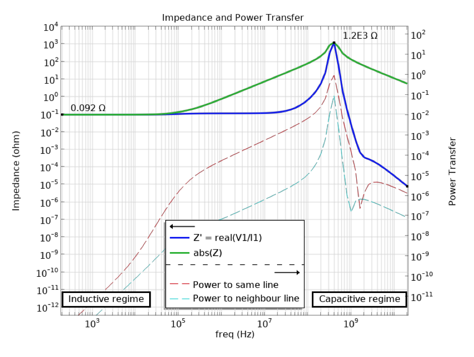
The resulting impedance at the inputs (solid lines) and power transfer to two of the four outputs (dashed lines). The LC resonance is visible around 400 MHz.
You can explore this model by downloading its related MPH file, CircuitExtractor_blog_case3_ResistorsNetworkStationaryCurrentVerification.mph, from the Application Gallery. A lot more could be said on the physics of transformer-like structures having a large capacitive coupling. If you are interested in this, check out our blog post “Computing Transformer Equivalent Circuit Parameters”.
Conclusion
In this blog post, we have explained the use of the Circuit Extractor add-in and shown how it can be used for converting electromagnetics simulations into a lumped representation.
Several cases have been analyzed here, and many more cases are supported. The add-in can be inspected and modified to suit your specific modeling needs. For example, we recently tested extending the add-in to model a full multiphysics Joule heating problem. We decided to use the lumped electrical circuit description to obtain currents because — as shown in this blog post — this approach includes the same high accuracy as given by FEM, but allows for much faster simulations. Simultaneously, we extended the circuits description, keeping the information from the extracted spatial distribution of the currents. This resulted in a fast and accurate simulation accounting for the effect of spatially varying currents and temperature.
Next Step
Learn how to manually access and start using the new Circuit Extractor add-in here, and then try out the models featured in this blog post via the button below:
Related Resources
- Explore these related resources on the COMSOL Blog:
- Check out these related tutorial models:
Support for implementation of the ODB++ Format was provided by Mentor Graphics Corporation pursuant to the ODB++ Solutions Development Partnership General Terms and Conditions (https://odbplusplus.com/design/). ODB++ is a registered trademark of Mentor Graphics Corporation.




Comments (4)
Phanindra Reddy Ravi
August 29, 2022Thank you for your nice blog.
In the Case 3: RLC Frequency-Domain Extraction for PCB Coil Model
What if the conductors are not grounded (conductor numbers 1,2,3,4, 9,10,11,12 are given a ground condition in addition to terminal condition) but connected to another conductor which is not of type coil but a rectangular trace ?
Cesare Tozzo
September 1, 2022 COMSOL EmployeeCases 3 is setup specifically to handle also such situation. In particular it offers a large the freedom in specify grounds and path of currents in such a way to distinguish different scenario. More specifically:
* in this setup ground conditions in “Magnetic Fields, Currents Only” does rule only where currents are exiting but not capacitance
* “Electrostatics” ground is specified (on boundaries # 3, 10, 1912, 2099 that are disjoint from current carrying conductors); this condition is ruling capacitive coupling of conductor to ground; mutual capacitance is essentially that of floating conductors (and it is also essentially what is drawn)
* you can similarly handle very different configurations; e.g. you can decide to have a solid object that is both collecting currents and act as capacitive ground; if you have a conducting manifold with multiple input and a common output, the condition may be a lot easier to handle by means of a sweep done by a “Magnetic and Electric Fields” interface, instead of using this setup; we may be blogging about this too; in the meanwhile you may appreciate the blog https://www.comsol.com/blogs/computing-transformer-equivalent-circuit-parameters/ where ground conditions are set in a specific way that is very smart for that specific device, and feel free to reach out us at support@comsol.com
Muhammad shafi Kp
May 16, 2023Dear sir
I hope you well. My name is Muhammad Shafi kp , and I am writing to seek guidance regarding the simulation of electric fields and potential distribution in COMSOL Multiphysics, specifically in version 6.1. I am particularly interested in studying the behavior of these fields around a plate and cylinder within a uniform electric field.
As an aspiring researcher in the field of electrical engineering, I am keen to deepen my understanding of electric fields and potential distributions. After conducting some research, I came across COMSOL Multiphysics, renowned for its capabilities in simulating and analyzing various physical phenomena. Therefore, I believe it would be an excellent tool to investigate the behavior of electric fields and potential distributions in this particular scenario.
I kindly request your assistance in providing some guidance on how to set up the simulation in COMSOL Multiphysics (version 6.1) for studying the aforementioned scenario. Specifically, I am interested in:
Simulating the electric fields and potential distribution around a plate: I would like to understand the characteristics and behavior of the electric field and potential distribution in the vicinity of a plate within a uniform electric field. Could you please provide me with instructions on how to set up the simulation parameters, boundary conditions, and necessary physics interfaces to accomplish this?
Simulating the electric fields and potential distribution around a cylinder: Similarly, I would like to examine the electric field and potential distribution around a cylinder in the presence of a uniform electric field. It would be immensely helpful if you could guide me on the steps involved in setting up this simulation, including the appropriate physics interfaces and boundary conditions.
I understand that you may have a busy schedule, but any assistance or guidance you can provide would be greatly appreciated. If there are any specific resources, tutorials, or examples that you could point me towards, it would be immensely helpful for me to grasp the concepts and techniques required to achieve accurate and reliable simulations.
Thank you very much for your time and consideration. I eagerly await your response and look forward to embarking on this simulation journey with your guidance. Should you have any further questions or require any additional information, please do not hesitate to let me know.
Wishing you a wonderful day ahead!
Cesare Tozzo
May 17, 2023 COMSOL EmployeeHello Muhammad shafi Kp,
Thank you for your comment. I forwarded your message to our support team that will contact you via email to provide you with guidance. I invite you to browse our site where you will find
– tutorials such as https://www.comsol.com/support/learning-center/article/Introduction-to-Electro-Thermal-Mechanical-Modeling-10561/82
– multiple examples; I cite for your case https://www.comsol.com/model/tunable-mems-capacitor-123 dealing with electric fields around conductors, https://www.comsol.com/model/magnetically-permeable-sphere-in-a-static-magnetic-field-12735 dealing with body immersed in uniform fields, and
https://www.comsol.com/model/magnetic-brake-2014 dealing with physics of conducting moving bodies in external magnetic fields