

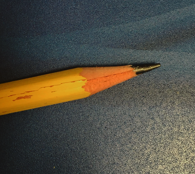
Does a new design come from a person or a process? We may imagine that innovators envision a design and then pick up their pencils to bring their idea to life. Of course, designers and engineers today might not use pencils, and they might not have a final design idea in mind. Instead, some designers use a process that comes up with new ideas for them — a methodology known as generative design (Ref. 1). Generative design is an umbrella term for a rule-based design process, typically powered by computational software, which generates forms that follow its rules. Today we discuss using an equation-based modeling process to generate a novel pencil holder design based on user-defined rules and values.
Pencils, Processes, and the Point of Generative Design
People are at the heart of the generative design process, and pencils are still useful, just as they’ve been since their familiar design first emerged in 16th century England, where they helped shepherds keep track of their sheep. Countless pencils (and pencil-enabled ideas) would follow. Note, however, that it wasn’t until the mid-19th century that pencils were attached to erasers!
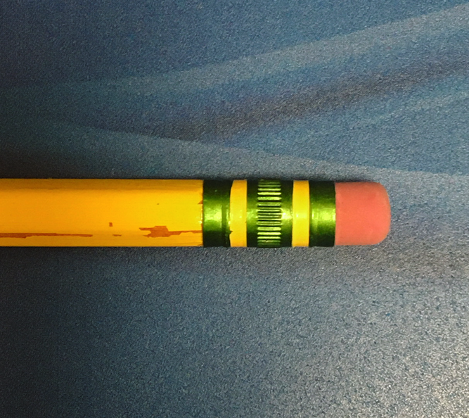
Hey, you two should get together! The first modern graphite pencils appeared in the 16th century, while rubber erasers are an 18th century invention. Decades more would pass before erasers were attached to pencils.
In hindsight, it’s easy to wonder why nobody thought of adding erasers to pencils sooner. An erasing tool seems like an obvious complement to a writing tool, but new ideas don’t necessarily appear when we might expect them. This elusive quality of human creativity is one reason why generative design is so powerful: It can help us discover better ideas, faster.
Generative Design, Topology Optimization, and Field-Driven Design
At the heart of generative design is a rule-based process for producing form. The person guiding the project sets the rules of the generative process, including values that will shape the desired result. The process then uses those values to generate forms that adhere to its rules. Crucially, the designer does not create formal options in advance and then use the process to evaluate them. Instead, the process itself generates multiple formal options. The user can then consider which options (all of which follow the user-defined rules) best serve the broader goals of the project.
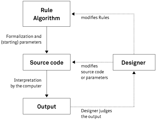
A schematic of the role of the designer in a generative design process, as created by an interdisciplinary team for the book Generative Gestaltung. Image by Hartmut Bohnacker, licensed under CC BY 3.0, via Wikimedia Commons.
Generative design methodology is well suited to 3D modeling and other additive manufacturing techniques, which can shape materials into unorthodox yet functional forms. Other terms, such as field-driven design and topology optimization, are used to describe various applications of generative design methods to engineering problems. The fields of field-driven design can encompass user-defined boundary conditions and simulated values in determining the rules guiding a generative process. The various terms help describe a designer’s priorities in setting rules to guide the generative process.
A generative design for a gyroid geometry.
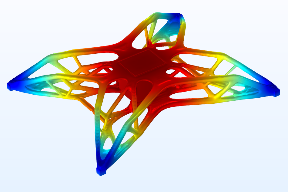
The topology optimization of a drone design, showing simulated displacement under load.
In a Digital Engineering article, Kristian Ejlebjærg Jensen of COMSOL explains:
“The fundamental difference between topology optimization and generative design is that topology optimization is driven by the physics of the problem, while generative design is more directly controlled by the designer’s own choices and requirements.”
The animation below shows how topology optimization iterates toward a stiff and lightweight design for a drone’s structure.
The process of topology optimization is illustrated for a drone. The designer can change the volume fraction and the minimum length scale. The designer has no other explicit control of the design, so the final form is primarily dictated by the details of the two load cases.
How Simulation Software Supports Generative Design
Simulation software, which is built on a foundation of finite element analysis (FEA), can support a generative design methodology. The solvers in the COMSOL Multiphysics® software interpret equations, expressions, and other mathematical descriptions to help generate a model. By adjusting these inputs, you can initiate a generative design process that targets specific priorities.
The rules that guide topology optimization, for example, may prioritize the efficient use of material to provide structural integrity. Topology optimization can also help engineers design a 3D-printed acoustic chamber for gaseous photoacoustic spectroscopy or microlattice structures for sound absorption.
While topology optimization can generate a design that meets certain objectives, other relevant priorities could favor a different formal solution. Consider the simulated heat sink designs shown below, which were generated using the Optimization Module, an add-on to COMSOL Multiphysics. The design on the left was generated by parametric optimization, which produced evenly sized and spaced heat-dispersing fins. Topology optimization, which applies a more granular and less restrictive generative process, produced the intricate form shown on the right.
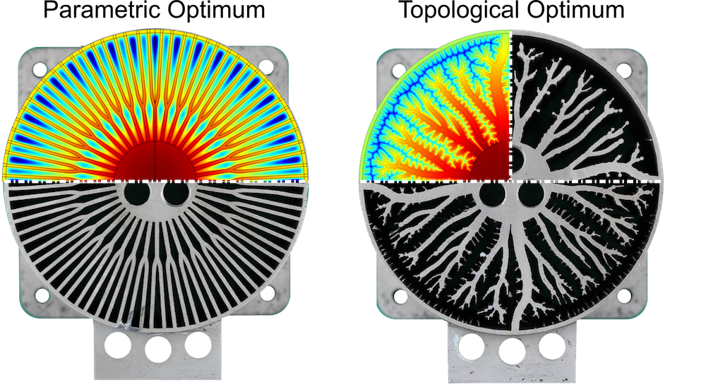
Heat sink designs generated by parametric (left) and topological (right) optimization. Image courtesy Fritz Lange.
Which design is better? The answer depends on “the designer’s choices and requirements,” as Ejlebjærg Jensen said in the quote above. Perhaps the simpler form is less thermally efficient, but cheaper to produce; this may be a more relevant metric to the overall goals of the project. Even as rules-based processes generate novel forms, the designer’s priorities must still guide the process of generative design.
With this in mind, let’s consider a pencil holder model, which demonstrates how the COMSOL® software can empower your own generative, field-driven design process.
A Field-Driven Design for a Pencil Holder
The Field-Driven Design of a Pencil Holder model demonstrates one way of using equation-based modeling for generative design by using the powerful mathematical expression capabilities of COMSOL Multiphysics.
The geometry of the pencil holder includes six parametric surfaces used to construct a domain. The rest of the geometry is defined by equation-based modeling and meshed by extruding a mapped mesh.
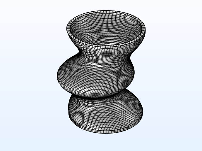
A mesh of cubic elements (as shown at left) defines the geometry of the pencil holder.
Form Generation with Equation-Based Modeling
The Coefficient Form PDE interface is used to define a Helmholtz filter, which generates two smooth fields on the boundary. (Learn more about data filtering via this interface in this previous blog post.) A Laplace equation is then used to transfer the boundary values to the volume. Finally, the fields are combined in an analytical expression, which defines the geometry. The designer can vary the parameters of the PDE and/or the expression to generate a different form, as illustrated by the animation below.
The animation shows the effect of changing three values: the volume fraction (spatially), the parameter controlling the angles of the braces, and the height of the upper and lower rim.
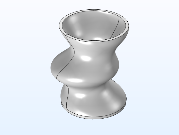
The final field can be exported as an STL file and then imported as a mesh part for further analysis.
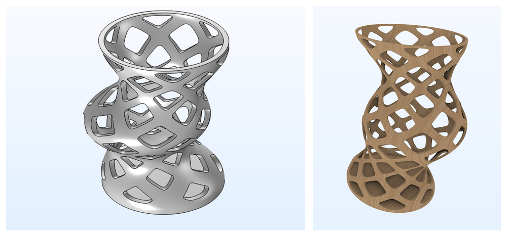
The pencil holder as rendered for STL export. The image on the right displays a wood texture, as applied by the Material Rendering feature built into the COMSOL® software.
In the pencil holder example, the design is driven by a more-or-less analytically given field. However, COMSOL Multiphysics will allow you to use other field quantities, such as stress, fluid velocity, or an electric field, to drive the design. The possibilities are virtually endless.
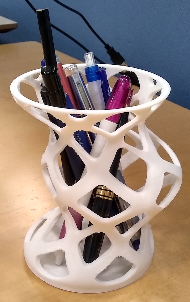
A 3D-printed version of the generated pencil holder design.
Next Steps
Get started with generative design by downloading the tutorial model for the pencil holder via the button below:
Further Reading on Generative Design
- Designing the Sound Absorption of Microlattice Structures
- Comparing Optimization Methods for a Heat Sink Design for 3D Printing
- Analyzing Topology Optimization of a Photoacoustic Spectroscopy Cell
Reference
- K. Wong, “Optimize or Generate?,” Digital Engineering, 2021, https://www.digitalengineering247.com/article/optimize-or-generate/


Comments (0)