
Material deposition is an essential ingredient in certain manufacturing processes, including welding and additive manufacturing. Say that you want to simulate such a manufacturing process. A challenge that you will face during the simulation is depositing material in a way that introduces it in a state of zero stress. Here, we look at the Activation functionality in the COMSOL Multiphysics® software and how it facilitates the simulation of material deposition.
Why Activate or Deactivate Material?
Imagine that you want to simulate a structural material that is in a molten state and then solidifies. Alternatively, the material is initially solid and then melts. This can be the case when you want to simulate manufacturing processes such as arc welding, selective laser melting, and selective laser sintering — the last two being common additive manufacturing methods.
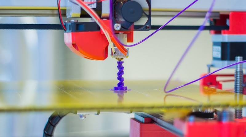
Material activation is useful when simulating additive manufacturing processes. Image of a 3D printer by Jonathan Juursema — Own work. Licensed under CC BY-SA 3.0, via Wikimedia Commons.
You can use the Activation node to activate or deactivate material in a simple manner during a simulation. As a note, the Activation node is available in the add-on Structural Mechanics Module and MEMS Module as of version 5.4 of COMSOL Multiphysics®.
Activation of Material: The Naive Approach
One approach to emulate that material is structurally absent is to simply reduce its elastic stiffness to a point where it becomes negligible. This way, the rest of the structure is free to deform without “feeling” the structurally weaker material. This is a viable approach as long as we have no desire to actually activate material.
A problem arises if we try to activate the weak material by simply restoring its stiffness to the nominal level at some point during the simulation. When the stiffness is restored, any strains present in the activated material will suddenly produce stresses. In most situations, this is not a desired effect when activating material. Instead, material should be activated in a state of zero stress. This is more physical, as we usually want to emulate that material is deposited or solidified.
Activate Material in a Stress-Free State
The Activation node avoids the problem of the artificially produced stresses described above. This node reduces the stiffness of the inactive material as described before, but, importantly, it also removes any elastic strains that are present at the instant of activation. Simply put, material is activated in a state of zero stress.
The Activation node is located under the Linear Elastic Material node, as shown in the figure below, and it is available for the Solid Mechanics and Membrane interfaces.
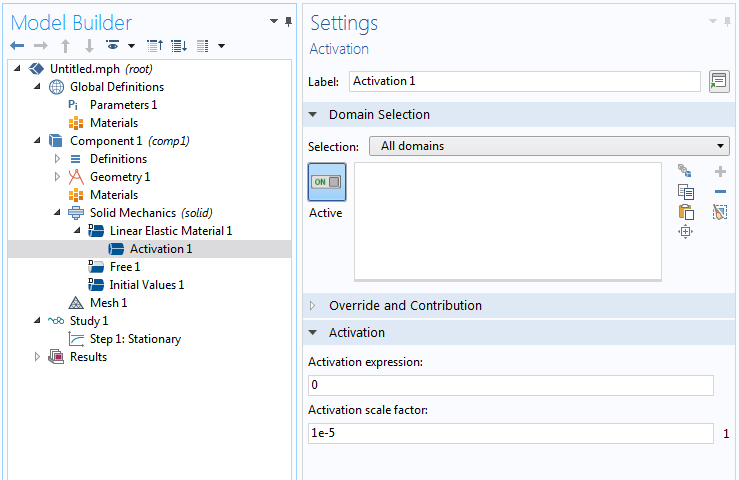
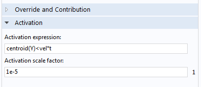
The Activation feature and its Settings window.
The Activation panel of the Settings window contains two settings, namely:
- Activation expression
- Activation scale factor
The Activation expression setting is a logical expression that you define. It is used to determine whether the material is active or not, and it is defined per integration point of the mesh elements. For example, an activation expression that reads T<T_s says that the material is active if the expression is logically true (when the temperature, T, is less than the solidification temperature, T_s) and inactive otherwise.
The Activation scale factor setting defines the factor that multiplies the elastic stiffness to emulate that material is not present. It has a default value of 10-5, but you can change it if you wish. However, a value that is too low could make the stiffness matrix ill-conditioned.
Two built-in variables are provided to describe the active/inactive state, namely:
isactivewasactive
The variable isactive indicates the current active/inactive state of the material, while the variable wasactive indicates whether the material has been active at any previous point during the simulation. In the case of a Solid Mechanics interface with the tag solid, the variable describing the current state of the material is called solid.isactive. The wasactive variable can be used to simplify the formulation of the activation expression in some situations, as we will see below.
Note: If a material undergoes multiple activation/deactivation events, the elastic strains are removed at every instant of activation. This means that the material is always activated in a state of zero stress, regardless of its history, including past activations or deactivations. Inelastic strains, such as plastic strains, are not removed.
Let us look at some examples of how to use the Activation node.
Example 1: Pointwise Activation
As a simple 2D example, suppose that you want to gradually activate a material in the y direction as time, t, progresses. The imagined “activation front” travels at a velocity, vel, and the region of active material is therefore given by Y<vel\times t. It is entered as the activation expression, as shown in the following figure.
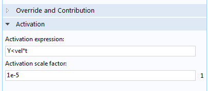
Activation expression for pointwise material activation.
To illustrate this, consider a solid quadrilateral element with four integration points (Gauss points), as in the figure below. With the activation expression above, each integration point is activated individually by evaluating the activation expression. This means, in practice, that a single mesh element can be partially active if it has more than one integration point.
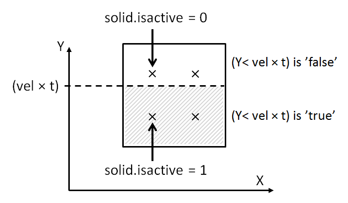
Activation of individual integration points in a mesh element.
Example 2: Elementwise Activation
Now, consider a case where you want to activate entire mesh elements, and not on an individual integration point basis. To do so, you need to phrase the activation expression so that it evaluates equally for every integration point in each mesh element. This can be done using the centroid operator. The activation expression that was used in the previous example is modified, as shown in the following figure. The coordinate Y is now evaluated at the mesh element centroid, which means that the activation expression will evaluate to the same value for all of the integration points in the mesh element.
Activation expression for elementwise material activation.
Inside the mesh element in the figure below, the activation expression is fulfilled for the element centroid, and therefore all four integration points are active.
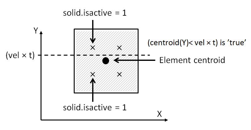
Activation of all integration points in a mesh element by using the centroid operator.
Example 3: Using the Previous State of Activation
Suppose that you want to simulate a laser cladding process where a filler material is melted and deposited over time. In this situation, the current position of the laser beam defines the location where material is currently deposited. The region of previously activated material is defined by the entire trajectory of the laser beam from the start of the process. (For details on how to model the movement of a laser beam, you can read this blog post on modeling moving loads and constraints.) The variable wasactive can be used to avoid having to describe this trajectory mathematically. You can express an activation expression for this situation schematically as:
(logical expression describing the current position of the laser beam) || solid.wasactive
which states that the material is active if the “logical expression describing the current position of the laser beam” is true or if the material has been active at any previous time (or parameter step) during the simulation. If the activation expression is used without the wasactive variable, the material would become inactive once the laser beam has passed, which is likely contrary to what is intended.
Visualizing the Results
Suppose that you have simulated a time-dependent process where material is deposited over time. It may be interesting to display results only for the active parts of a domain. You can do this by using the variable isactive as the Logical expression for inclusion in the Filter node, as shown in the figure below. Note that depending on the chosen fulfillment type, the isactive filtering may show slight differences compared to the underlying isactive variable defined at the integration points of the mesh elements.
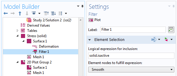
Using the Filter node to display only active parts of a domain.
Concluding Thoughts on the Activation Node
In this blog post, we have described different ways of using the Activation node to activate material during a simulation. The Activation node makes it easy to simulate the deposition of material in simulations of different types of manufacturing processes, such as welding and additive manufacturing. If you want to examine a model that uses the Activation node, click the button below to see the Thermal Initial Stresses in a Layered Plate example in the Application Gallery.


Comments (23)
Chamara Kumara
December 18, 2018Can we do this for heat transfer problems with a moving heat source. IF yes. where can I find this activation option?
Mats Danielsson
December 18, 2018 COMSOL EmployeeHi!
The Activation node is only available for the Linear Elastic Material. However, you can use the variables “isactive” and “wasactive” in other contexts, too. See Example 3 above.
Mats
Chamara Kumara
December 18, 2018Hi Mats
Thanks for the reply.
Suppose that we have a moving Gaussian volumetric heat source. So where do we have to specify this “wasactive”. Do we define this in in the analytic function that we will define for the heat source or we just simply define it under the heat source node.
Simple example would be highly appreciated 🙂
Yu Zhang
January 15, 2019Hi, Mats:
This is a very interesting and useful topic to me. Now I am a bit confused by the centroid operator. Could you please further explain this operator at a more mathematical level? Is it correct if I regard it as a volume averaged value of a variable over a single element?
Thank you so much for your help and time.
Mats Danielsson
January 16, 2019 COMSOL EmployeeHi Chamara Kumara!
Well, it depends on what you intend to do.
Suppose that you already have a description of the path that the heat source takes. If your modeling approach is to activate material when the temperature exceeds a certain value, then you probably want to keep the material active even if the temperature decreases subsequently. An example would be if you want to emulate welding, where the material should remain even after the heat source has passed. In that situation you could use the “wasactive” variable in the Activation expression to “remember” that the heat source has activated material at a certain location previously.
Or, as in Example 3, if you do not solve the actual heat transfer problem, it may be sufficient to simply track where the heat source is, and where it has been.
As a side note, you can use the Activation variable “isactive” from a Solid Mechanics or Membrane interface to modify material properties such as heat conductivity.
Mats
Mats Danielsson
January 16, 2019 COMSOL EmployeeHi Yu Zhang!
No, to quote the COMSOL Multiphysics Reference Manual: “The centroid operator evaluates the expression expr at the centroid of the mesh element to which the point belongs.”
Mats
Andrea Roberto Calore
January 28, 2019Dear Mats,
how to have an activation front moving in 2D with a square waveform pattern (as in Fused Deposition Modelling)?
Thank you.
Mats Danielsson
January 30, 2019 COMSOL EmployeeHi Andrea!
This sounds similar to another question that was asked above (regarding moving heat sources). See if that helps. Otherwise, you can contact Comsol Support if your problem is very specific.
Mats
Andrea Roberto Calore
January 30, 2019Dear Mats,
true, thank you for your reply.
However, I do not fully understand example 3. I already have a mathematical expression for the path of my heating source and I would like to study the heat transfer as it moves. I have read that I can use the variables isactive and was active also elsewhere but where should I type my activation condition? Still in the Activation node under the liner elastic material node even though I want to study the heat transfer?
thank you.
Mats Danielsson
January 30, 2019 COMSOL EmployeeHi Andrea!
The activation expression only pertains to the Linear Elastic Material under which the Activation node is used. So if you phrase an activation expression using information about the position of the heat source (which you know) or in terms of the computed temperatures, this will determine how the linear elastic material will be activated during the simulation. Now, for material that is not active, it is likely that you want to modify not only the elastic properties, but also properties such as thermal conductivity. For this, you can use the variable isactive. Suppose that you want to emulate that the thermal conductivity changes depending on whether the material is active or not. An expression for the thermal conductivity could then be entered as k0+k*solid.isactive, where k0 is small compared to k.
Mats
Andrea Roberto Calore
January 30, 2019Dear Mats,
my apologizes but I cannot find the answer to my question in your reply. I would like to model how deposited material as in example 3 heats the air around. As such, the material is deposited over time. I thought the Activation node was the answer but this belongs to the Linear Elastic MAaterial only. Where should I then use my activation expression? Thank you.
Andrea Roberto Calore
February 6, 2019Dear Mats,
I successfully implement the activation node simulating the deposition process. Though, I have a doubt on how to simulate the temperature front. I tried by giving the plain extrusion temperature to the initial values node of the heat transfer in solids and liquids physics but the freshly activated (deposited) material is colder than expected. Thank you for your help.
Brianne Christopher
February 6, 2019 COMSOL EmployeeHello Andrea,
Thank you for your comment!
Please contact our Support team for additional help with your modeling.
Online Support Center: https://www.comsol.com/support
Email: support@comsol.com
Thank you!
Farid Vafadar
May 2, 2019Hi Mats!
Is it possible to simulate FDM (fused deposition modeling) process with Comsol Software, in a case to determine the residual stresses and deflection due to filament thermal activity?
If Not, is there any helpful software? As far I know, for doing this in ABAQUS or ANSYS, it requires using some subroutines.
Sincerely yours,
Farid Vafadar
Mats Danielsson
May 3, 2019 COMSOL EmployeeDear Farid,
To within the limitations of the Activation functionality you should be able to compute stresses in a deposition process model. If you have very specific questions that relate to the particular phenomena you wish to capture, please contact our Support team for additional help with your modeling.
Online Support Center: https://www.comsol.com/support
Email: support@comsol.com
I cannot comment on other software, I am afraid.
Mats
Vladimir Buelvas
February 27, 2020Hello:
I am trying to buid one embankment layer by layer and I heard someone spoke about the Activation node and I have 5.2 version But that version does not have that module, How could I model this cases if changing flow, stress, heat properties with the time, also boundary conditions are changing with the time. Thank you
parker harry
October 17, 2020These tricks are really good and helpful. So everyone tries this method which told in the blog. So keep a share. Also, I am a technician of laptop repair dubai in UAE. If anyone needs help just visit: https://atdoorstep.ae/dubai/laptop-repair
Zhengyu Shi
August 3, 2022Hi,
is it possible to add initial stress on the activation domain to emulate the conditon that adding layers with residual stress?
thank you!
Mats Danielsson
August 3, 2022 COMSOL EmployeeHi,
Initial stresses are removed when a material is activated, causing stress-free activation. But you should be able to use the External Stress feature, and add a stress multiplied by some boolean expression corresponding to the activation condition. If the Activation expression is para>4, then you could add a stress, for example, as 45[MPa]*(para>4).
Mats
Zhengyu Shi
August 4, 2022Hi Mats
Thanks a lot for your reply.
comsol’s function is so complex, even though i have using it for several years.
Sourav Mahato
January 12, 2023i tried to do this technique in my additive manufacturing simulation. the activation expression works but only is stress result section, i want it to show in temperature result section.Also i cant add heat in between the layers, for example i have two rectangular block one above another for 1st layer i want the upper cuboid to be inactive and add a boudry heat source in the top face of 1st cuboid but it says not applicable so i tried doing it on the above cuboid hoping it will pass directly below but it doesnt. Can anyone help me im stuck in this for like 1month
The Than
May 14, 2024Could you please gset me how to active and deactive element on Cylinder coordinate system
Thanks you very much.
Mats Danielsson
May 15, 2024 COMSOL EmployeeHello!
The “Activation expression” takes any expression you enter, so in case of for example axisymmetry, you could use the radial coordinate R, etc. Of course, any activation event will also be axisymmetric.
The Activation feature is not aware of any specific coordinate system – it tries to evaluate the Activation expression that you enter.