
How fast can you set up a multibody system model? When modeling a large mechanical system with several components, have you ever wanted to model most of them as rigid bodies? While setting up a gearbox model, is it tedious to enter input parameters for each gear in the assembly? The COMSOL Multiphysics® software provides a way to eliminate repetitive modeling steps. See how the Automated Model Setup functionality in the Multibody Dynamics interface can automate and speed up your modeling process.
Why Automate Your Multibody Model Setup?
From a simple slide-crank mechanism to a robust truck-mounted crane machine, any assembly of connected bodies used for transferring force or motion can be thought of as a multibody system. Simulating the dynamics of multibody systems with large motion is always of interest to engineers, especially those who work with automobiles and other machinery, where the results of a multibody dynamics study have often served as guidelines for preliminary designs.
Along with its increasing popularity, multibody dynamics modeling poses some challenges to engineers, mainly when modeling large, real-life systems. As any typical vehicle or machine can have a sizable number of components, the model setup for such systems demands a large amount of time. When dealing with large models, there is also a chance of manual errors during model setup. Under such conditions, it would be advantageous to develop methods that can eliminate all repetitive modeling steps by automating them. Such an approach not only speeds up your modeling process but also provides an error-free model for the analysis.
Automating the Setup of a Multibody Model in COMSOL Multiphysics®
For quickly setting up large multibody systems for simulation, COMSOL Multiphysics introduced a new functionality in version 5.5. Using the Automated Model Setup functionality available in the Multibody Dynamics interface, you can easily generate multiple rigid domain and gear physics nodes at once from the model geometries.
As shown in the screenshot below, a new section called Automated Model Setup is added in the Multibody Dynamics interface Settings window. It contains two buttons:
- Create Rigid Domains
- Create Gears
If you want to automate Rigid Domain node generation, press the Create Rigid Domains button. Similarly, for automatic creation of Gear nodes, press the Create Gears button.
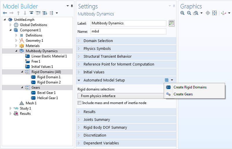
The Automated Model Setup functionality in the Multibody Dynamics interface. You can press either the Create Rigid Domains or Create Gears button to automatically generate the corresponding physics nodes.
When either button is pressed, a node group containing the corresponding physics nodes is added in the Model Builder. Note that the actions of these buttons are independent of each other. The section also contains some additional inputs to control rigid domain generation.
In the following sections, we will look at the Create Rigid Domains and Create Gears buttons in detail, illustrating with examples.
Editor’s note on 12/13/22: In version 6.1, the Rigid Domain feature has been renamed to Rigid Material.
Automating Rigid Domain Creation
In this section, we will learn about the modeling of large rigid body systems and the use of Automated Model Setup functionality to speed up the model setup for such systems.
As mentioned above, a general multibody system is an assembly of connected bodies, either rigid or flexible. While bodies undergoing size or shape changes under the action of external loads are treated as flexible, stiff bodies with negligible deformation (zero for all practical purposes) are considered rigid bodies.
In the real world, there is no ideal rigid body, but for most practical purposes, we generally assume the relatively stiff components as rigid bodies. This is especially true when we are not interested in the detailed stress analysis of these components, but rather the overall system dynamics. COMSOL Multiphysics supports the modeling of rigid bodies using the Rigid Domain material model functionality available in the Solid Mechanics and Multibody Dynamics interfaces.
Suppose you want to understand the dynamics of a large multibody system with lots of rigid components. For performing a quick preliminary analysis, you decide to model each rigid body with a given mass and moment of inertia using the Rigid Domain and Mass and Moment of Inertia functionalities. However, for a moderately large system, adding these nodes separately to each of the geometry components is a time-consuming task. Additionally, assigning selections for complex geometries is prone to manual errors. To make things easier in such scenarios, COMSOL Multiphysics provides a simpler way: Using the Create Rigid Domains button, all of the abovementioned steps can be completed at once with a single click of a button.
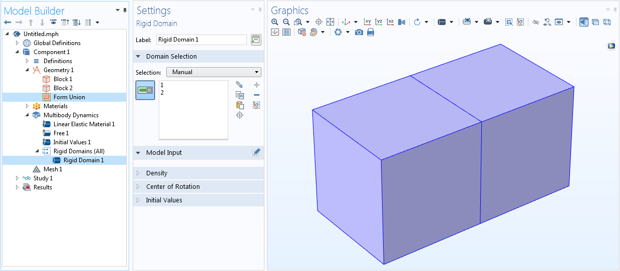
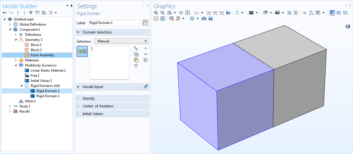
You can use the Create Rigid Domains button for both 2D and 3D models, which adds separate Rigid Domain nodes to each of the geometrically disconnected objects. As geometry information is critical in rigid domain creation, you need to build your model geometry in such a way that all domains that are part of a rigid body should be in a geometric union. Note that when your model contains objects that are geometrically disconnected, the geometry sequence finalization step should be set to Form Assembly from the default Form Union. A typical use of Form Assembly is when you model any system with large relative motion between parts.
Left: The two block geometries, which are in union, are treated as one object, hence only one Rigid Domain node is created. Right: When the blocks are geometrically disconnected, separate Rigid Domain nodes are created on each of the objects.
By default, the Create Rigid Domains button adds a Rigid Domain node on all of the domains selected in the physics interface. There can be cases where you want to model only some part of the geometry as a rigid body and the rest as flexible. The Three-Cylinder Reciprocating Engine model is one such example, where all parts except the central connecting rod have to be modeled as rigid bodies. You can address such cases through the Rigid Domain Selection menu, which lists all domain selections available. Create a new domain selection of all rigid components, if it does not already exist, and set it as the input in the Rigid Domain Selection. In such cases, the rigid domain creation is restricted only to those objects in the selection.
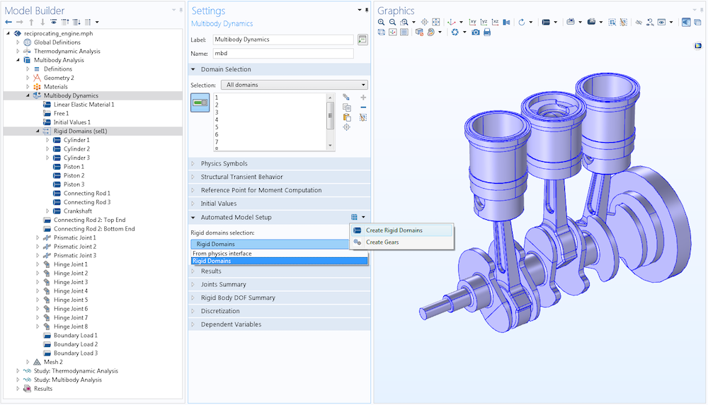
In the Three-Cylinder Reciprocating Engine model, a new domain selection called Rigid Domains, containing all domains except the central connecting rod, is created. In the Automated Model Setup section, the new selection is set as the input for the rigid domain creation. This restricts the rigid domain creation only to the objects contained in the list.
As discussed earlier, the Create Rigid Domains button can also be used to add a Mass and Moment of Inertia node to each of the autogenerated rigid domains. For that, you need to check the Include mass and moment of inertia box in the Automated Model Setup section. This will set the mass density of all rigid domains as zero and add a Mass and Moment of Inertia node, where you can input a lumped mass and moment of inertia into each of the rigid domains.
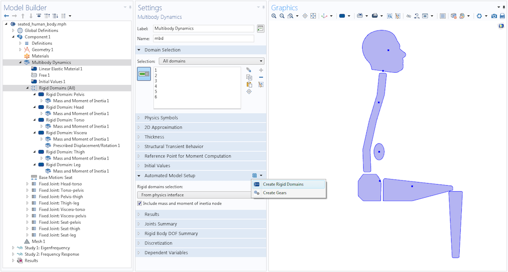
In the Biomechanical Model of the Human Body in a Sitting Posture model, the Create Rigid Domains button is used to add separate Rigid Domain nodes on each of the six body parts. The lumped mass and moment of inertia of each part is modeled through automatically added Mass and Moment of Inertia nodes.
Automating Gear Modeling
Another important addition in the Automated Model Setup functionality is the Create Gears button for the automated generation of gear nodes in the Multibody Dynamics interface.
From automobiles and toys to wind turbines and winding clocks, gears are integral to most machines. Gears of different types and sizes are used in all of these machines to transmit mechanical power between different parts. The ability of a gear system to change speed or direction of motion between shafts is the result of the successive engagement of teeth between adjacent gears.
Unlike other mechanical transmission systems, such as belt drives and chain drives, a gear drive can be used to transmit power between parallel as well as nonparallel shafts. The ability to transmit high torque, compact size, and high efficiency are additional desirable features of gears, which makes them an ideal ingredient for many industrial machines.
While designing a machine with gears, it is critical to perform numerical modeling. Compared to analytical calculations and rules of thumb, a detailed numerical model can always offer an optimized solution to most practical problems. COMSOL Multiphysics provides an easy way to numerically model different gear types and the connections between them. Using the different gear features available in the Multibody Dynamics interface, you can model a variety of:
- Gear types
- Bevel gears
- Helical gears
- Spur gears
- Worm gears
- Racks
- Helical racks
- Spur racks
It is also possible to model the contact and subsequent transfer of power between gears using features like Gear Pair, Rack and Pinion, and Worm and Wheel. In a blog series on gear modeling, we give an overview of these features in the COMSOL® software with some interesting example models.
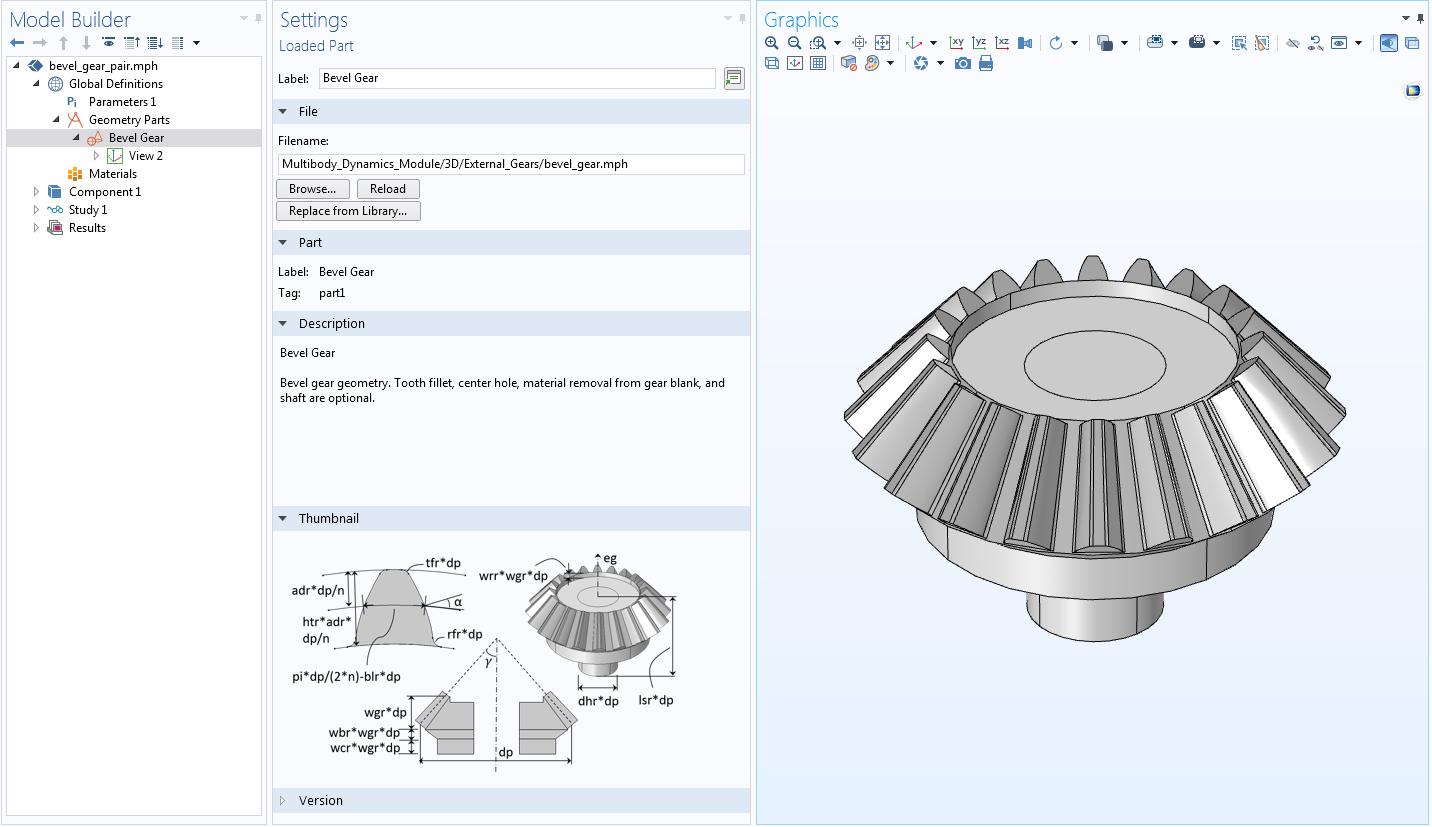
The first step in gear modeling is the geometry creation. It is always possible to import your own gear geometry and model it using the appropriate gear features available in the Multibody Dynamics interface. A much more robust alternative available in COMSOL Multiphysics is to generate a parameterized gear geometry using built-in parts in the Part Library. With an extensive set of input parameters available to customize the shape of the gear tooth and gear blank profile, you can create your own gear geometry in 2D or 3D. Compared to an imported geometry, the geometry created from the part has the flexibility to be modified at any stage of the modeling process, just by changing its input parameters.
Left: A parameterized bevel gear geometry created with gear parts included in the Part Library. Right: Different input parameters are used to customize the gear tooth and gear blank shape.
After creating the gear geometry, the next step is to add the corresponding gear feature. Before COMSOL® version 5.5, you had to manually add the appropriate gear features, assign domain selections on the geometry, and enter all relevant input parameters matching with the gear geometry parameters. With the Create Gears button, available as of version 5.5, these steps are completely automated, which in turn makes your gear model setup very fast. By pressing the Create Gears button, a set of gear nodes can be automatically added with proper domain selections and input parameters, which are grouped under a node group in the physics interface.
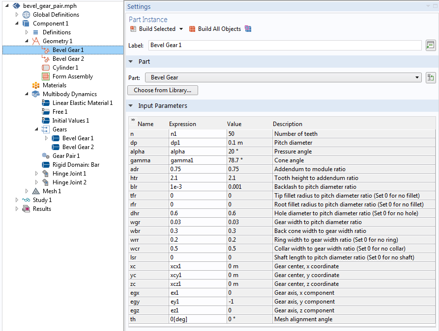
To illustrate the automated gear node generation, let’s have a look at the Forces and Moments on Bevel Gears model available in the COMSOL Multiphysics Application Library. The model geometry consists of two bevel gear geometries created from the Part Library. When the Create Gears button in the Automated Model Setup section is pressed, a Gears node group is created under the physics node. As shown in the figure below, it contains two Bevel Gear nodes corresponding to each of the bevel gears in the geometry.
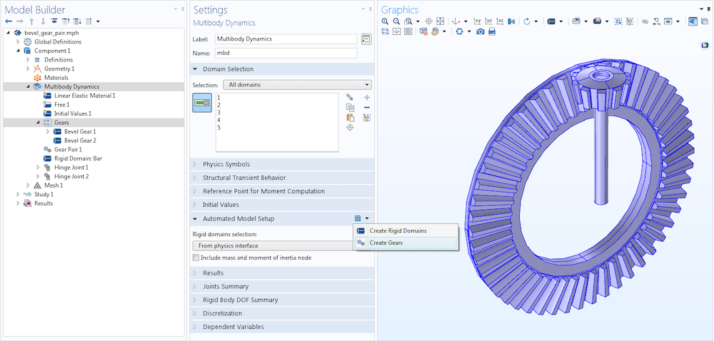
In the Forces and Moments on Bevel Gears model, the two Bevel Gear nodes are added automatically using the Create Gears button. Both the Bevel Gear nodes are also automatically grouped in a node group for a compact Model Builder view.
For each of the automatically created gear nodes in the Settings window, the input parameters (such as the number of teeth, pitch diameter, pressure angle, cone angle, gear axis, and center of rotation) needed for the gear model are automatically filled by taking values from the corresponding gear geometry input parameters. This eliminates the need to manually enter each parameter, thus speeding up the gear system model setup.
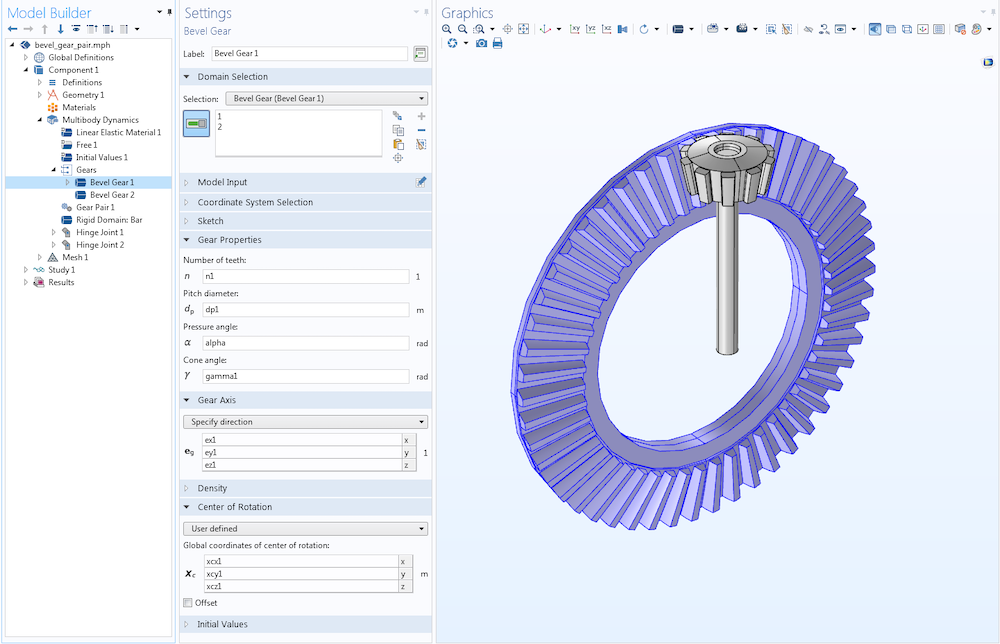
Selections are assigned automatically to domains corresponding to each gear part present in the geometry. Additionally, the values of gear parameters required for modeling are taken from the geometry part (listed in the figure above) and automatically entered.
Like the Bevel Gear nodes in this example, you can automatically add any other type of gear node, provided you have a matching geometry created from the Part Library. Take a look at the Dynamics of Helical Gears model to see the automatic generation of helical gears using the Create Gears button.
Next Steps
Try using the Create Rigid Domains and Create Gears buttons to set up your multibody models and see the ease in your modeling workflow. Also, explore other new functionalities and improvements available in the Multibody Dynamics Module as of COMSOL Multiphysics version 5.5:




Comments (0)