
When dealing with radiative heat loads in a thermal model, we need to be careful to understand how the incident thermal radiation interacts with surfaces. If dealing with a system that does not have any refractive elements, then the capabilities of the Surface-to-Surface Radiation interface within the Heat Transfer Module give us modeling capabilities to handle both diffuse and specular reflections, absorption, and transmission. Let’s learn more…
This is the second blog post in a series on modeling radiative heat transfer using the COMSOL Multiphysics® software. Read Part 1 and Part 3 here.
Infrared Radiation Incident on a Surface
We are dealing with graybody radiation, so we start with the relationship: \alpha + \rho_d +\rho_s = 1 and describe the surface behavior in terms of two properties:
- Emissivity, \epsilon, which is the ratio of radiation emitted by a surface as compared to a perfect emitter, as introduced in our blog post on modeling emissivity
- Diffuse reflectivity, \rho_d
The surface absorptivity equals emissivity, \alpha = \epsilon and thus the specular reflectivity is \rho_s = 1-(\alpha + \rho_d). An absorptivity of zero means all radiation is reflected, and \alpha = 1 would mean that all radiation is absorbed. Although we can only approach these limits for true materials, sometimes the concept of a perfect absorber or perfect reflector (either diffuse or specular) is useful for modeling purposes.
The figure below shows the cases of incident collimated radiative flux:
- Being perfectly absorbed
- Being diffusely reflected with the possibility of some absorption
- Being specularly reflected with the possibility of some absorption
- Experiencing absorption as well as diffuse and specular reflection
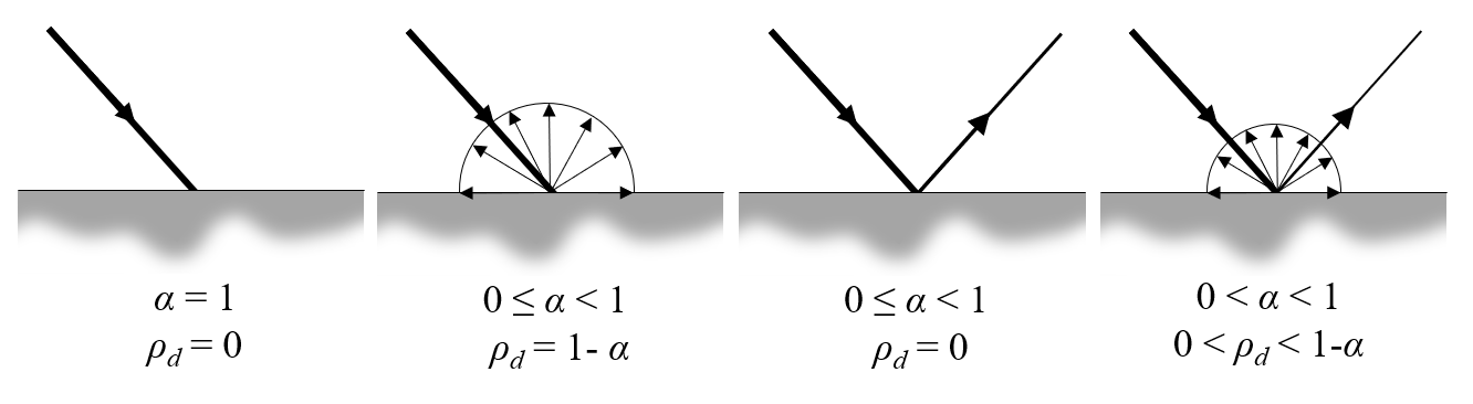
A beam of collimated radiation incident on a surface for various combinations of absorptivity (emissivity) and diffuse reflectivity. Emission, due to a non-zero surface temperature, is omitted from these figures.
Modeling of specular reflection requires using the Ray Shooting method within the Surface-to-Surface Radiation interface. When this method is used, the Opaque Surface feature lets us enter diffuse reflectivity and surface emissivity, and the surface emissivity (absorptivity) can include an angular dependence. The other methods, the Direct Area Integration method (which is used only for smaller models without any obstructions to view factors) and the Hemicube method, do not admit specular reflection. Thus, they offer solely a Diffuse Surface feature, which lets us enter emissivity and compute the diffuse reflectivity from \rho_d = 1-\epsilon. For the example we are about to look at, we will use solely the Ray Shooting method, since it can address all the cases we are interested in.
To gain intuition, let us consider a thermal model of a vacuum chamber as shown below. There are two parts to this chamber, with the smaller containing a hot object that emits thermal radiation, infrared (IR) light. A narrow opening will let a little bit of this radiation through to illuminate the other part of the chamber. We will look at how this incident radiation is absorbed and reflected by an object placed at the center. Since the opening is long and narrow, the radiation passing through is nearly collimated.
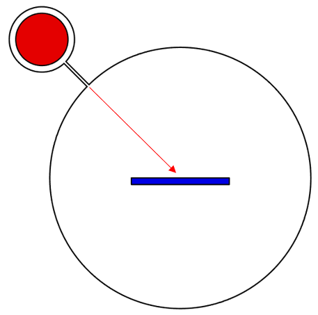
A vacuum chamber with two sections and a small opening that allows some nearly collimated thermal radiation through.
The walls of the chamber have the emissivity (absorptivity) set to one and are held fixed at a temperature of 0 K, thus acting as perfect absorbers of the radiation reflected from the object at the center. Since we are only interested in computing the interaction of the incident radiation with the surfaces and do not want to model any other modes of heat transfer, such as conductive heat transfer within the solid, we can use solely the Surface-to-Surface Radiation interface and omit the Heat Transfer in Solids interface from our model.
We will also fix the temperature of the target part at 0 K, so that it does not emit any radiation by itself. Although this is a bit artificial, it lets us focus solely on how the radiation emitted from the hot part will be absorbed and reflected off of our target part.
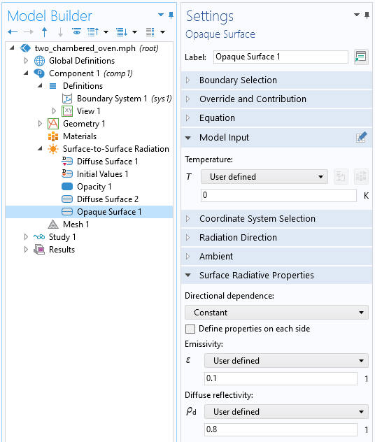
Setup for a mixed specular/diffuse surface. Setting the temperature to 0 K means the surface will not itself radiate.
The plots below show the radiation reflected off of the bottom surface and absorbed by the chamber walls under different combinations of settings. As we can see, the patterns differ depending on the absorptivity and diffuse reflectivity.
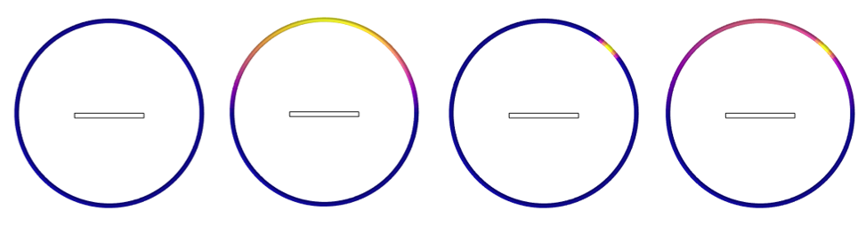
Plot of the thermal radiation on the walls of the chamber. This illustrates how the thermal radiation is reflected off of the target part. From left to right: perfect absorption, diffuse reflection, specular reflection, and mixed diffuse/specular reflection.
Modeling of Specular Reflection from Curved Surfaces
Next, let’s modify our model and place a perfectly specular round object at the center, as shown in the image below. The incident radiation will be reflected onto the walls of the surrounding chamber, but to model this reflection accurately requires increasing the geometric discretization order. This setting is distinct from the discretization of the fields and requires two changes to the settings, as shown in the screenshots below. These settings only affect the Ray Shooting method.
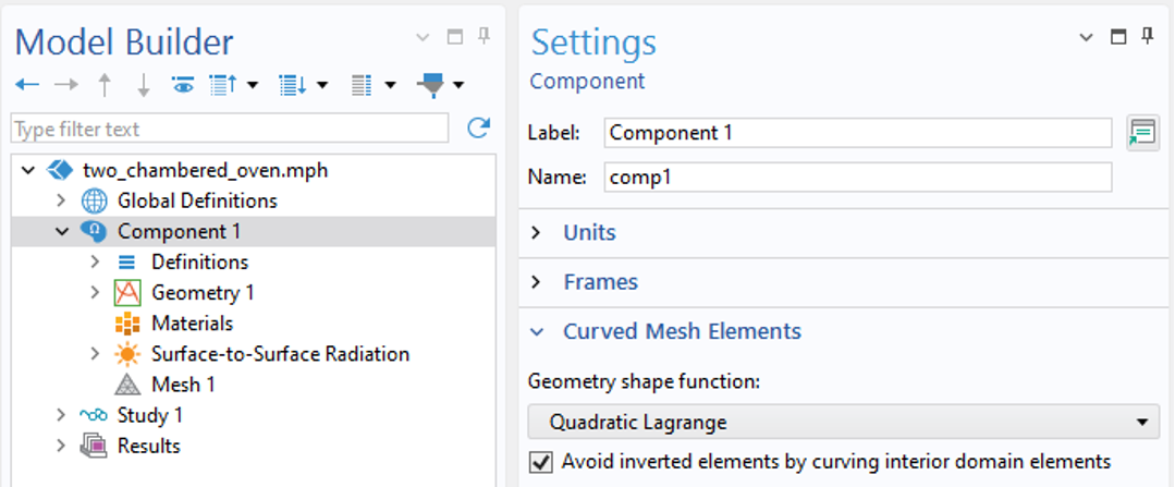
Component-level settings that affect the geometry shape used in Ray Shooting.
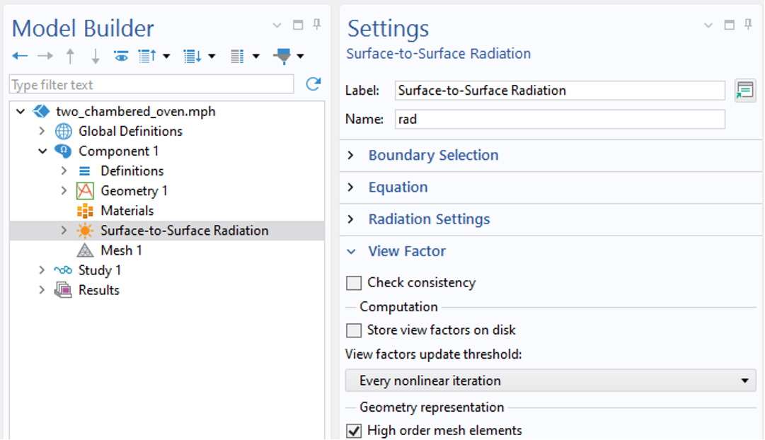
Enabling High order mesh elements will use the geometry discretization order to compute reflections.
Note that the default discretization of the Surface-to-Surface Radiation interface is linear, and would thus treat the round object as faceted, with each element boundary representing a small flat mirror. This is fine to do as long as all, or most, of the surfaces are planar. However, if significant reflection from curved surfaces is expected, then the geometric discretization order should be increased such that the distribution of the reflected radiation becomes more smooth.
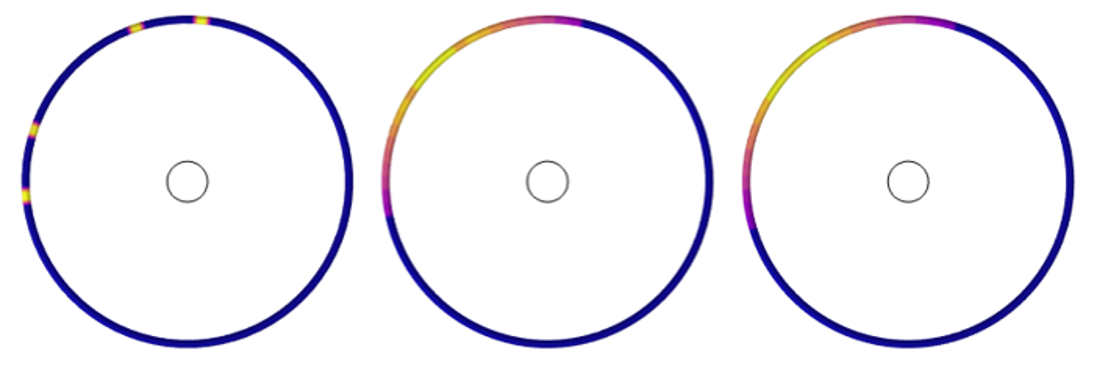
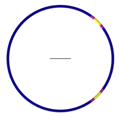
Plots of the reflected radiation away from a small circular object, using linear, quadratic, and cubic geometry discretization.
Modeling Semitransparency
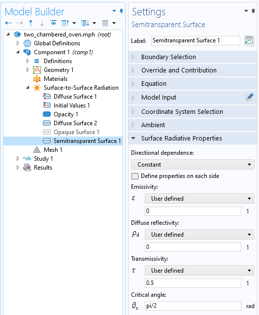
Finally, let us modify our example and consider a thin and flat object that is semitransparent, meaning that it will absorb, reflect, and transmit radiation. Under the restrictions that the refraction is unimportant, and that the object is thin, this case can be addressed via the Semitransparent Surface feature when using the Ray Shooting method. This feature additionally introduces a Surface Transmissivity property, \tau, which describes what fraction of the incident radiation is specularly transmitted: \alpha + \rho_d +\rho_s +\tau = 1. An additional Critical Angle setting provides a threshold below which no transmission will occur, only specular reflection.
The Semitransparent Surface feature splits the incident radiation into a reflected and transmitted component.
We can observe, in the image below, how setting emissivity and diffuse reflectivity to zero and transmissivity to 0.5 will lead to a 50/50 split of the incident radiation with specular reflection. If there is any absorption by the surface itself, this will be treated as a boundary heat load.
Incident radiation on a semitransparent surface is split into a reflected and transmitted component.
It is important to note the refraction is not accounted, so no lensing effects can be modeled. To model rays both reflecting and refracting through dielectric materials, the functionality of the Ray Optics Module can be used.
Closing Remarks
We have looked at the reflection of radiation off of opaque and semitransparent surfaces and the modeling considerations for simulating curved reflecting boundaries. Keep in mind that absorption and reflection of radiation happens in concert with emission of radiation from surfaces at finite temperature, as addressed in Part 1 of this blog series on modeling radiative heat transfer: “Modeling Emissivity in Radiative Heat Transfer“.
What we have not addressed so far is exactly how the software computes the radiative exchange between surfaces. To understand this computation it is necessary to go over the concept of view factors, the topic of the next article. Stay tuned!
Editor’s note: This blog post was updated on December 23, 2025, to include a discussion of the settings required to accurately model specular reflection from curved surfaces.


Comments (5)
Ivar KJELBERG
February 4, 2022Hi Walter,
Thanks again for a nice and instructive BLOG, such an App to solve all those cases would be a nice physics course exercise 🙂
One thing I have noticed, when teaching these concepts, is that the statement “alpha = epsilon” is hard to accept for many.
The main reason, I believe, is that all these surface parameters: alpha, tau, epsilon, rho_s and rho_d etc. are very strongly wavelengths dependent, and that the alpha = epsilon applies only if we consider the same spectral band pass.
Furthermore, when we talk about blackbody radiation of T[K] (whatever T) we are in fact also talking about spectral bands, narrower than the 0-INF limit, so often when we talk i.e. about solar irradiation we talk about the solar absorption alpha_sun, and the re-emitted radiation is mostly in the thermal regime, hence the epsilon is for a very different band pass, hence the two might not be equal (as the wavelengths considered are not the same).
This is well explained in your earlier BLOG from almost a decade now : https://www.comsol.com/blogs/thermal-modeling-surfaces-wavelength-dependent-emissivity/.
Sincerely,
Ivar
Ozan Celik
February 18, 2022Dear Walter,
Thank you for this nice Blog post. I found myself wondering how the hot object that emits the IR radiation (or the collimated IR beam source) was implemented in this model. Could elaborate a bit further on that?
Kind regards,
Ozan Celik
Walter Frei
February 18, 2022 COMSOL EmployeeHello Ozan,
The hot object (red circle in the second figure) was set up as an emitter as described in Part 1 (https://www.comsol.com/blogs/modeling-emissivity-in-radiative-heat-transfer/) The source is not, itself, collimated, but the narrow opening between the chambers is what results in a (nearly) collimated source.
Rana
October 13, 2023Is it possible to model grey body radiative transfer if the materials have a wavelength and temperature dependent absorption coefficient?
Walter Frei
October 16, 2023 COMSOL EmployeeHello Rana,
Yes, just keep in mind that absorptivity equals emissivity, and that when you enter a value for the wavelength-dependent emissivity, that can also be an expression which is temperature-dependent.