

If bubbles in a microfluidic device become stuck, it can cause the device to malfunction. Bubble entrapment depends on several factors, including the geometry and flow characteristics of the microchannel, as well as the surface properties of its walls. To study these aspects, Veryst Engineering modeled a bubble in a microchannel using the COMSOL Multiphysics® software. Today, we look at their results, which shed light on the device geometries and contact angles that lead to bubble entrapment.
Studying Bubble Entrapment in Microfluidic Devices
Bubble entrapment is a common problem in microfluidic devices, as bubbles often become stuck in microchannels. This interrupts the path of the fluid, creating disruptions in the flow and negatively affecting the performance of the device. For example, the presence of bubbles can result in incorrect readings in microchannel sensors or block the formation of jets in inkjet printers. Bubbles can’t always be avoided or removed by design, so the solution is to prevent bubbles from getting stuck in the microchannels of microfluidic devices.
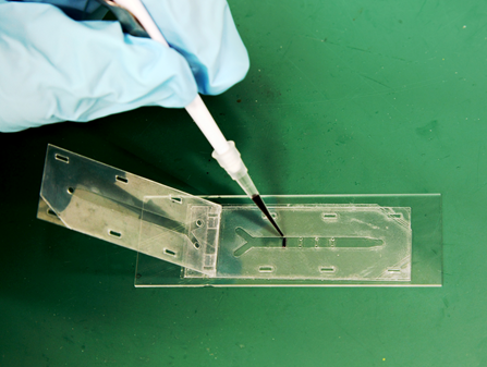
A simple microfluidic device.
Preventing bubble entrapment starts with the design of the microfluidic device. There are several factors influencing bubble movement through the microchannel, including the geometry of the channel, surface properties of the walls, and fluid flow characteristics. To better understand the effect of these aspects, researchers can use simulation to find the optimal conditions for ensuring that bubbles successfully pass through the microchannel. They can then design microfluidic devices that have a reduced risk of bubble entrapment.
To study these factors, Veryst Engineering — a COMSOL Certified Consultant — modeled a bubble moving through a microchannel with COMSOL Multiphysics.
Modeling Bubble Entrapment in COMSOL Multiphysics®
For their analyses, Veryst Engineering created a model using the level set method in the CFD Module, an add-on to COMSOL Multiphysics, and the Multiphase Flow interface. They chose to model a 0.3-mm bubble in a 1-by-2-mm microchannel that is mildly restricted in the middle. The bubble’s initial position is near the bottom of the channel and it moves upward with the fluid flow. The average fluid speed in the microchannel is ramped up from 0 to 50 mm/s in the first 10 microseconds of the simulation.
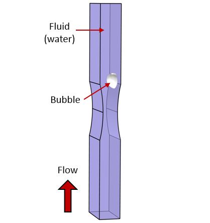
The bubble in the microchannel geometry. Image courtesy of Veryst Engineering.
For their model, the engineers first took the surface tension between the bubble and surrounding fluid into account. They also accounted for the surface properties of the microchannel walls, such as whether they were hydrophilic, neutral, or hydrophobic. The engineers assumed that the walls have a neutral contact angle with the bubble, except for in the constrained section of the microchannel.
Note that contact angle hysteresis — the difference between the advancing and receding contact angles — increases the chance of the bubble getting stuck. This effect was not taken into account in the model.
Simulating the Bubble’s Movement in the Microchannel
The team from Veryst then modeled the bubble at two different contact angles. The first simulation shows the bubble at a 22.5º contact angle with the microchannel wall. As seen below, the bubble becomes stuck near the end of the constriction. This forces the fluid to move around the obstacle, resulting in a nonsymmetric velocity field.
The bubble at a 22.5º contact angle with the channel wall. Toward the end of the constriction, the bubble becomes stuck. Animation courtesy of Veryst Engineering.
In the second simulation, the bubble is at a 90º contact angle. It now moves smoothly through the constriction and continues moving through the microchannel.
The bubble at a 90º contact angle with the wall. The bubble successfully passes through the constriction. Animation courtesy of Veryst Engineering.
The bubble’s average speed in both simulations is compared below. As it moves through the constriction, the bubble’s speed quickly increases due to the reduction of the channel area, as shown between 0.05 and 0.1 seconds.
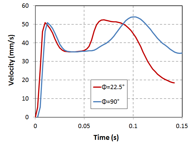
Comparison of the bubble’s average velocity for two different contact angles. Image courtesy of Veryst Engineering.
The Veryst engineers also compared the model predictions to analytical estimates. They showed that for this simple channel geometry and bubble size, a 22.5° contact angle at the constriction leads to bubble entrapment, while a 90° contact angle does not.
Next Steps for Simulating Bubble Entrapment
After finishing these simulations, the Veryst engineers applied this approach to a more realistic microchannel geometry. Their new results provided insight into various geometries and contact angles that result in bubble entrapment.
Knowing more about these factors can help to optimize the design of microfluidic devices that experience bubble entrapment. This in turn makes it easier for those who are working with these devices. With less chance of bubble entrapment, a microfluidic device’s performance is more reliable.
Further Resources
- Learn more about Veryst Engineering
- Explore other blog posts about how Veryst uses multiphysics simulation:
- See other examples of modeling microfluidic applications on the COMSOL Blog


Comments (1)
James Bao
June 29, 2023Hello, could you share your case file? thank you from the bottom of my heart.