support@comsol.com
MEMS Module Updates
For users of the MEMS Module, COMSOL Multiphysics® version 6.1 introduces two new multiphysics interfaces, contact modeling enhancements, and several new tutorial models. Read about these updates and more below.
Piezoelectricity and Pyroelectricity Multiphysics Interface
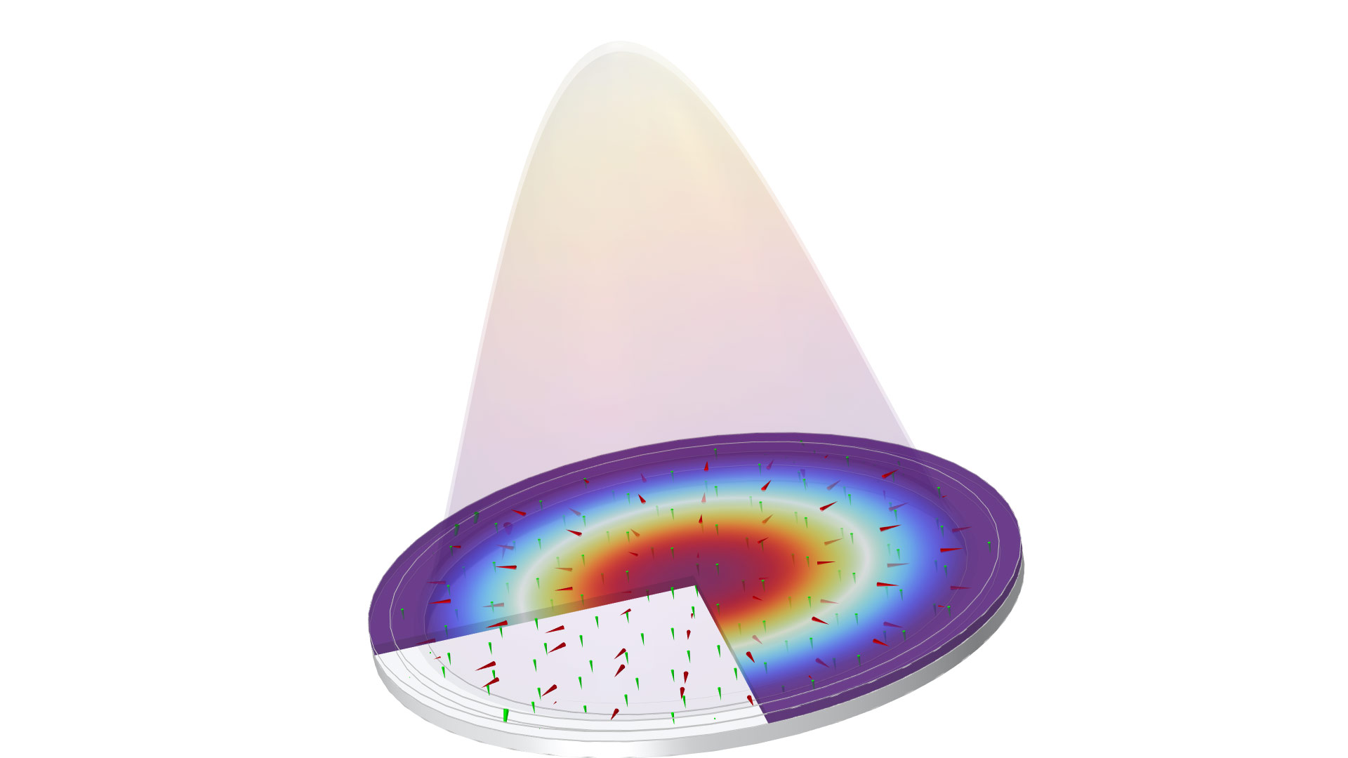
Under the AC/DC branch in the Model Wizard, a new Pyroelectricity multiphysics interface is available that combines the Electrostatics and Heat Transfer in Solids interfaces with the new Pyroelectricity multiphysics coupling. This can be used to simulate electric polarization in solid dielectrics resulting from variations in temperature. Similarly, under the Structural Mechanics branch in the Model Wizard, a new Piezoelectricity and Pyroelectricity multiphysics interface is available that combines the Solid Mechanics and Heat Transfer in Solids interfaces with the Piezoelectric Effect, Thermal Expansion, and Pyroelectricity multiphysics couplings. This can be used to simulate the electric polarization in piezoelectric material resulting from variations in temperature. This interface is used in the new Pyroelectric Detector model, which demonstrates the operation of a pyroelectric detector found in instruments for measuring laser energy.
New Tutorial Models
Normal Modes of a Biased Resonator — 3D Geometry from a GDS File
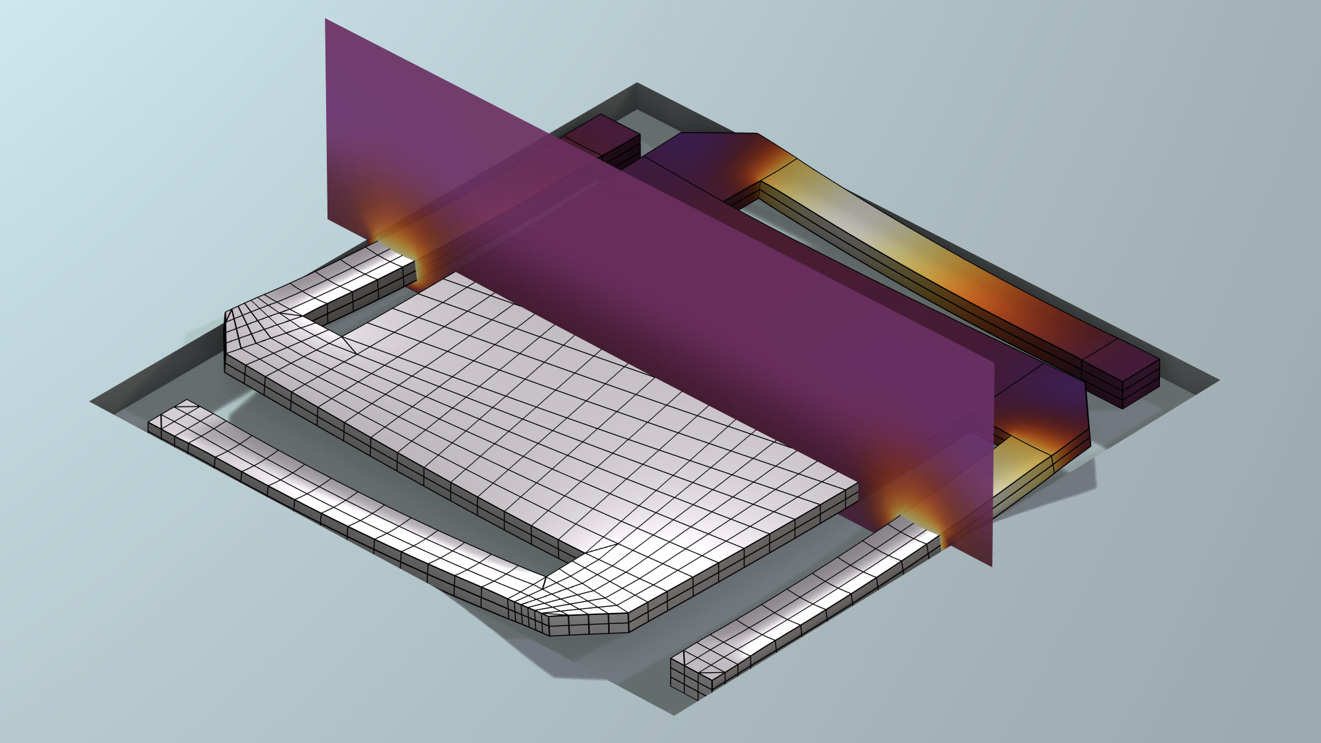
When modeling a MEMS or semiconductor device with complex 3D structure, the geometry buildup can be time consuming. Buildup can require assembling numerous primitive shapes in a procedure that does not correspond to the processes of depositing and patterning the distinct materials one layer at a time. This tutorial demonstrates how to build a 3D geometry more efficiently using a layer-by-layer method that replicates the fabrication of a MEMS device. By importing layouts from a GDS file using the ECAD Import Module and by using operations available in the Design Module, the number of parameters and steps for defining the geometry are greatly reduced.
You can download the model from the associated Application Gallery entry.
The structure of the biased resonator, built up layer by layer by importing a GDS file and using operations available in the Design Module.
Prestressed Micromirror Vibrations: Thermoviscous–Thermoelasticity Coupling
This new tutorial analyzes the operation of a prestressed micromirror, including the losses from the thermoelastic effect and the interaction with the surrounding air. It demonstrates the use of the Thermoviscous Acoustics-Thermoelasticity Boundary multiphysics coupling (available in the Acoustics Module) for modeling thermoviscous losses in acoustic–structure interaction problems in great detail. It captures the effect of a nonideal thermal condition at the fluid–structure interface, which is important in MEMS applications. The model also uses the Thermoelasticity interface to compute the mechanical losses from irreversible heat transfer driven by the thermoelastic effect, which can be particularly important for microscale structures.
You can download the model from the associated Application Gallery entry.
Capacitive Micromachined Ultrasonic Transducer
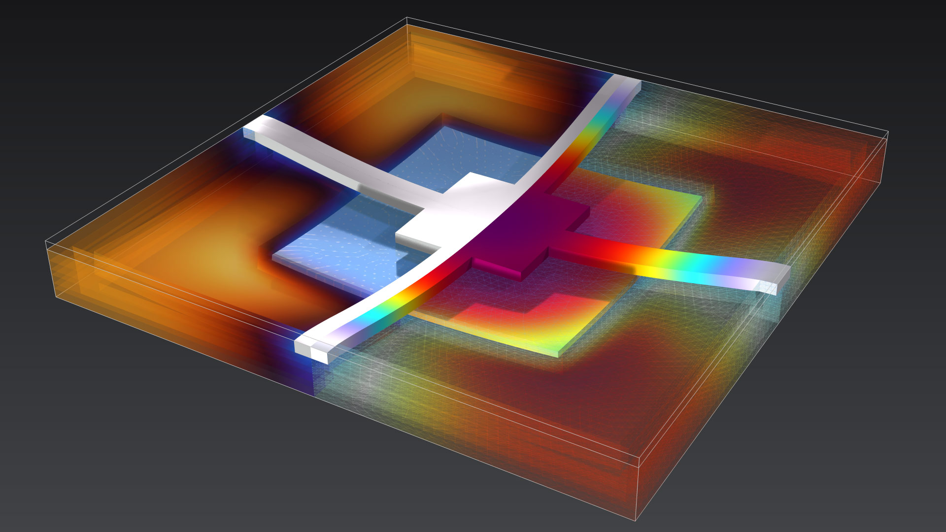
This model demonstrates the operation of a capacitive micromachined ultrasonic transducer (CMUT), a microscale receiver that converts ultrasound into electrical signal for high-resolution imaging applications. The transducer is connected to an external circuit, and a harmonic perturbation boundary load represents the ultrasonic energy. The model analyzes a CMUT design with optimized force-displacement characteristics for increased efficiency. An important metric to improve is the displacement uniformity factor, which can be calculated using a Frequency Domain, Prestressed study. This particular design advances a well-established medical imaging technology dominated by piezoelectric transducers and promises miniaturization and higher resolution. The device can be fabricated using well-established 0.35 μm complementary metal–oxide–semiconductor (CMOS)–MEMS process technology.
You can download the model from the associated Application Gallery entry.
Electrostatic Chuck
This model demonstrates the operation of an electrostatic chuck used to secure a wafer onto a temperature-controlled platform during wafer processing. The model computes the pressure-dependent cooling of the wafer using the Electromechanical Forces, Fluid-Structure Interaction, Nonisothermal Flow, and Thermal Expansion couplings. Electrostatic chucks (e-chucks) play an important role in various wafer-processing equipment. Instead of mechanical clamping, an e-chuck uses an electromechanical force to secure a wafer on a temperature-controlled platform during processing. In this model, an electrostatic force counters the pressure from helium gas flowing in the gap between the wafer and the e-chuck to provide efficient thermal conduction in an otherwise low-pressure environment.
You can download the model from the associated Application Gallery entry.
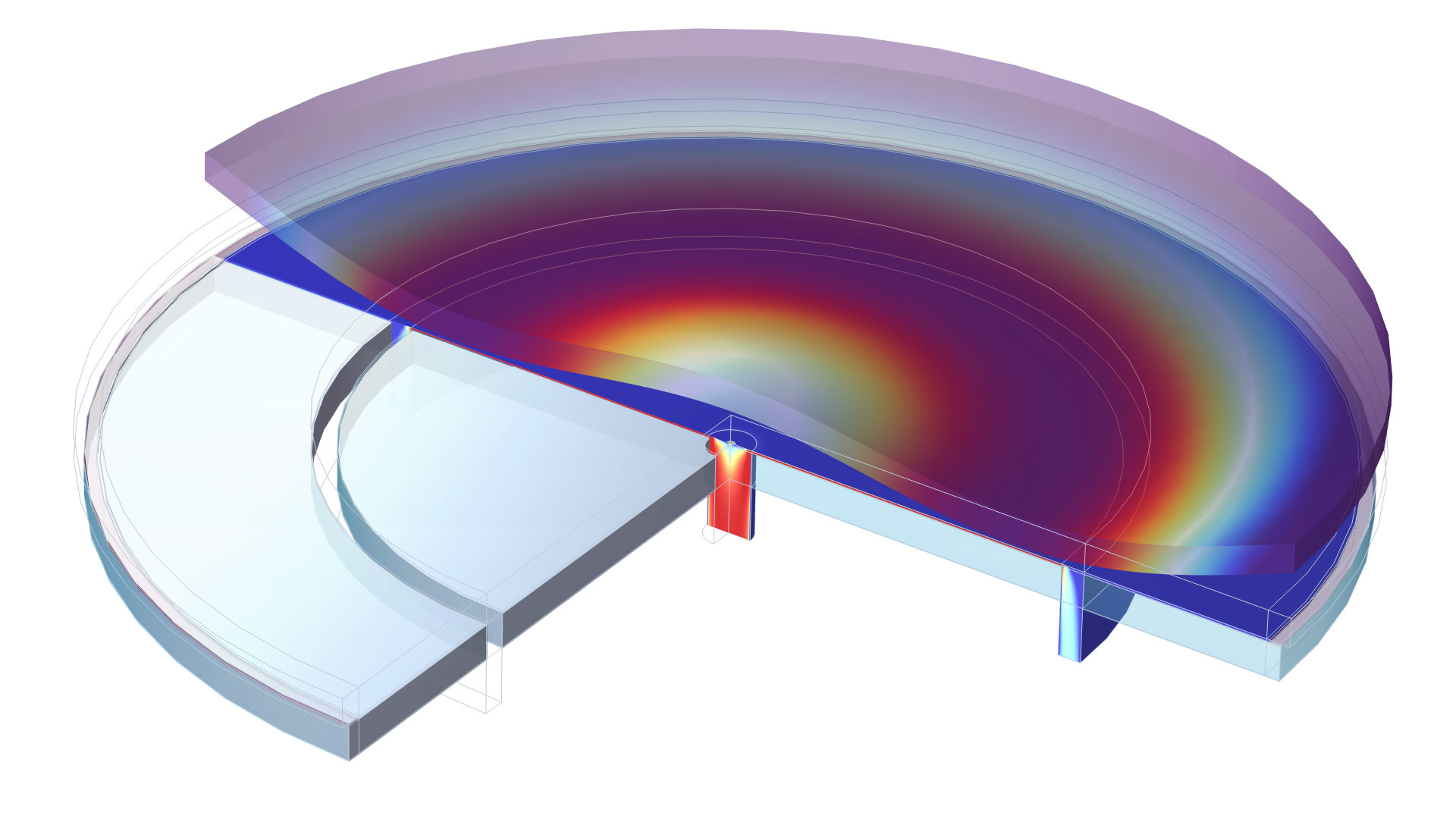
A model of the electrostatic chuck, showing cross section of the (exaggerated) deformed wafer. The colors on the chuck surface indicate wafer temperature and the colors in the gas channel indicate gas velocity.
Contact Modeling Enhancements
Several additions and improvements have been made to the contact modeling functionality.
- A new, faster contact search algorithm has been implemented. It is particularly advantageous for large 3D models.
- Nitsche's method, a new method for formulating the contact equations, has been added. It is a robust method that does not add any extra degrees of freedom.
- New, more stable formulations of the contact equations have been added for all contact models.
- Formulations for shells and membranes have been improved. Now, the actual surface on curved geometries is used.
- Support for self-contact has been improved. The formulation is now symmetric between the two sides of the contact pair.
Animation of an elastoplastic pipe forced into a conical hole. Self-contact occurs in several places.
Solid Mechanics Interface in 1D
The Solid Mechanics interface is now available for 1D and 1D axisymmetric components and does not require any additional product to use the basic functionality. In the transverse directions, different combinations of plane stress, plane strain, and generalized plane strain can be selected. There are several multiphysics applications in, for example, battery modeling, acoustics, and thermal–structure interaction where a 1D model can be useful for providing important insights into a physical phenomenon. Note that functionality for intercalation strains in batteries is included in the Battery Design Module. For more advanced 1D modeling, additional features are available when the Solid Mechanics interface is used in conjunction with the MEMS Module, Multibody Dynamics Module, or Acoustics Module.
A coupled thermal–structural problem with contact in 1D axisymmetry. Note that the underlying representation here is simply 1D elements along a line, whereas the results are expanded to a circular geometry for better visualization.
Numerical Testing of Material Models
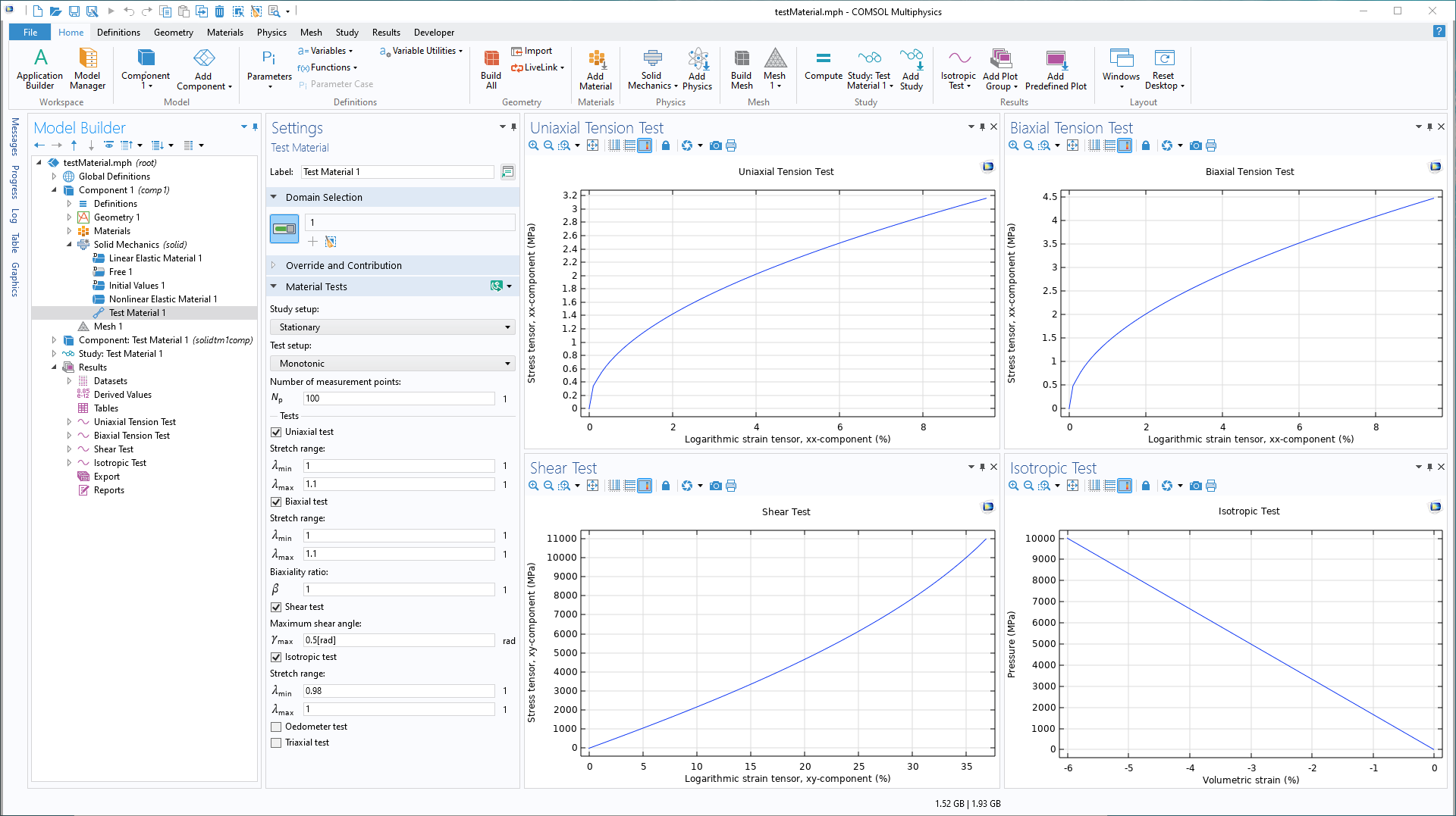
For complex material models, in particular those that are user defined, it is important to investigate how a model behaves under various loading conditions. The new Test Material feature in the Solid Mechanics interface can automatically set up a small one-element model with appropriate boundary conditions and study steps for several different loading conditions. The loading can be quasistatic or time dependent, monotonic or cyclic. You can see this new feature in the updated Isotropic Compression with Modified Cam-Clay Material Model and Primary Creep Under Nonconstant Load models.
Materials on Boundaries of Solids
A wide range of linear and nonlinear material models are now available to use on internal or external boundaries. This can be used to model glue layers, gaskets, or claddings, for example. Such layers can use different assumptions, ranging from full 3D to only in-plane strains. When you use the Composite Materials Module in conjunction with the Structural Mechanics Module to implement these models, the boundary materials can even be multilayered. The existing Heating Circuit model showcases this new addition.
Multiphysics Interfaces for Thin-Film Damping
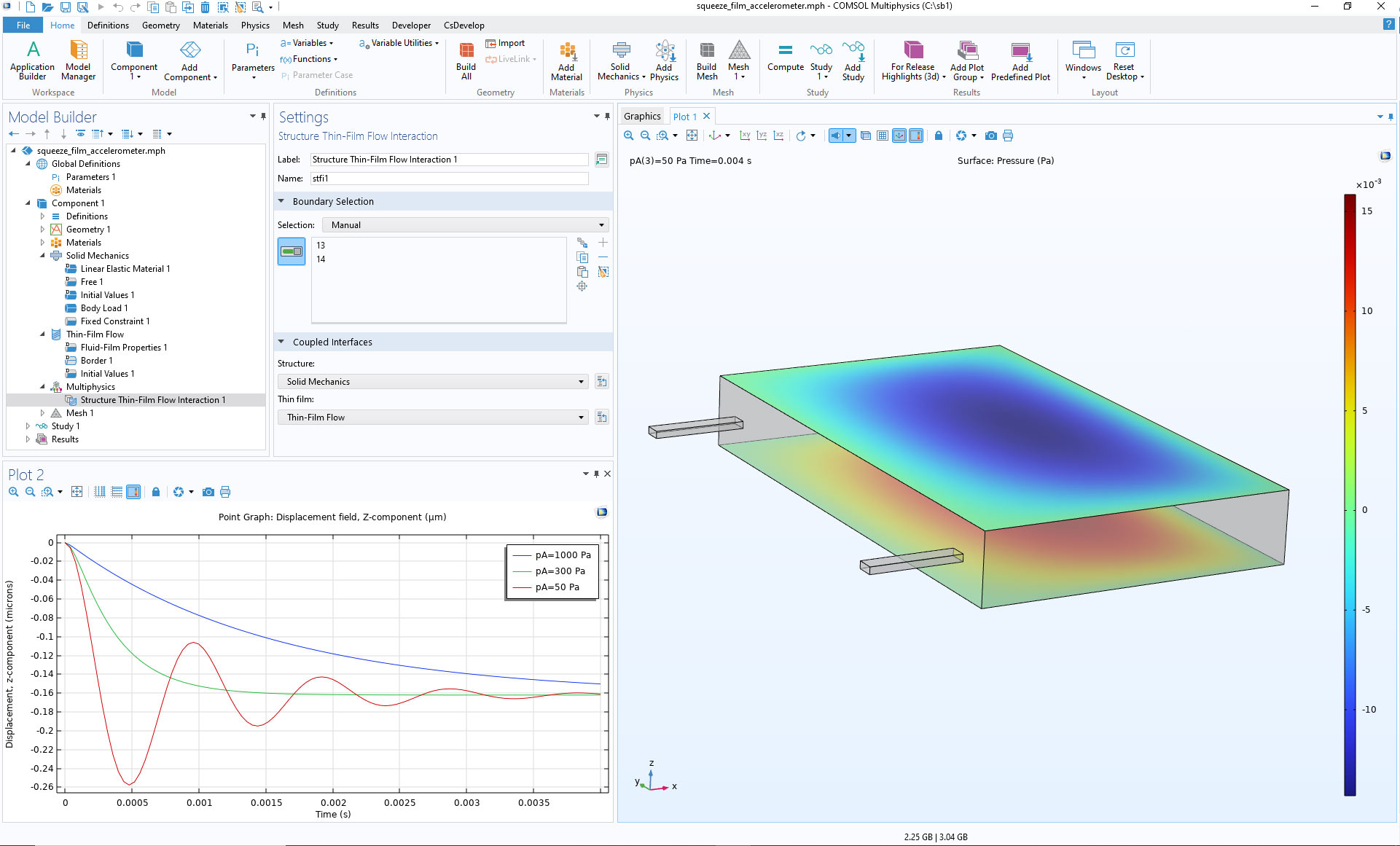
Two new multiphysics interfaces for thin-film damping have been added: Solid Thin-Film Damping and Shell Thin-Film Damping. They combine a Thin-Film Flow interface with Solid Mechanics or Shell, respectively. There are also two new multiphysics couplings that facilitate thin-film damping: Structure Thin-Film Flow Interaction and Shell Thin-Film Flow Interaction. These couplings are not limited to thin-film damping; you can also use them to model lubrication and cavitation, for example.
Buckling Analysis with Dead Loads
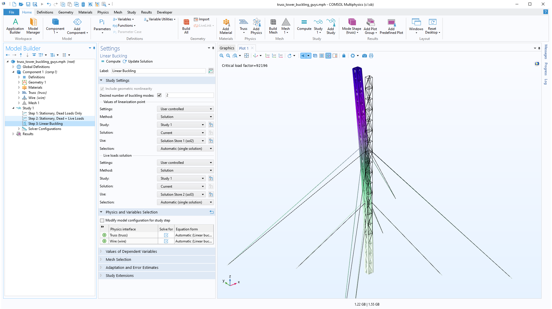
When searching for a critical buckling load, there are some situations where there are more than one system of loads, and one of them can be considered to be fixed. For example, a gravity load can be considered fixed (a dead load), whereas a service load can be considered not fixed (a live load). Even if you only want to compute the critical level of a service load, the dead load will still influence the risk of buckling. This type of analysis is now built in and can be viewed in the new Linear Buckling Analysis of a Truss Tower with Dead Loads model.
New Method for Connecting Assemblies
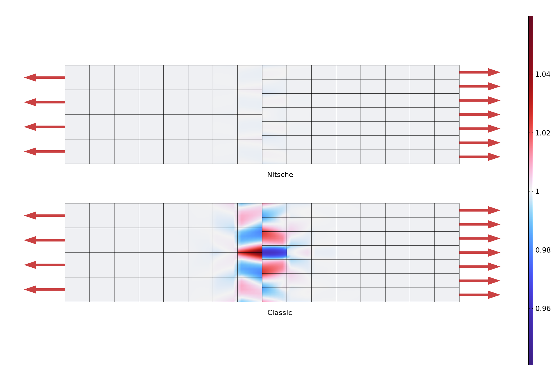
Nitsche's method has been added to enforce continuity between boundaries in assemblies. It has two important advantages when compared with classical pointwise constraints:
- It causes significantly less local disturbances in the solution when the meshes on the two sides are not conforming.
- Since no constraints are added, the numerically sensitive and sometimes computationally heavy constraint-elimination step is avoided.
Component Mode Synthesis Enhancements
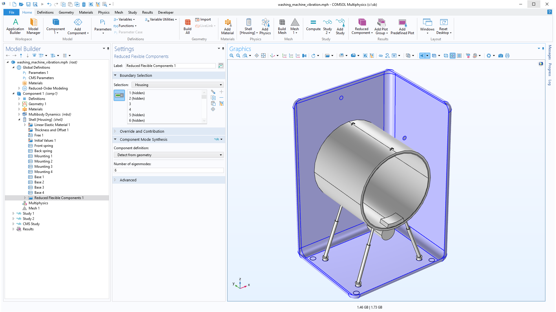
It is now possible to use shell elements in component mode synthesis (CMS) analyses. There are also several general improvements that make it easier to set up models for CMS analyses.
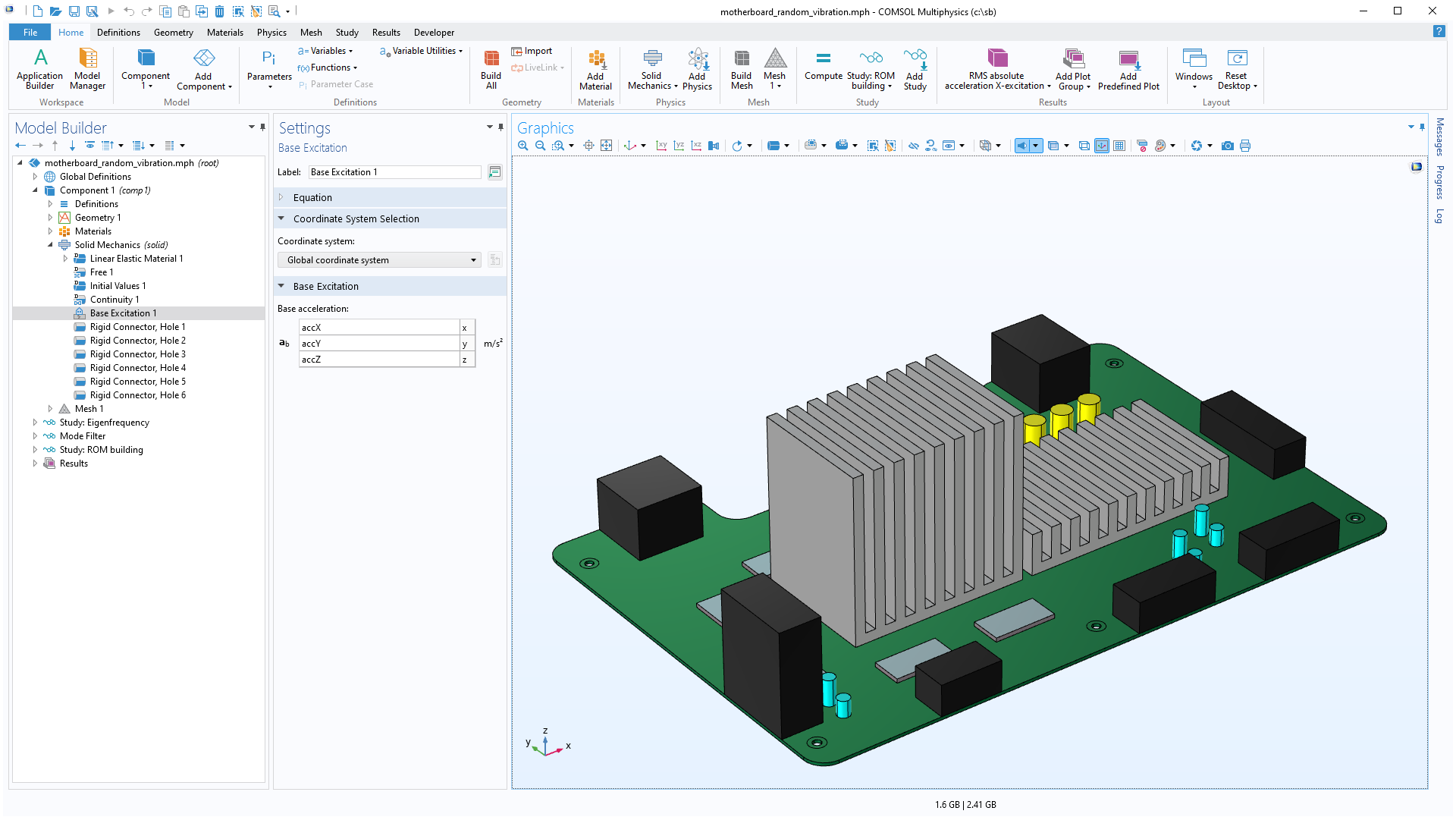
Base Excitation
It is common that the dynamic loading on a structure consists of a certain acceleration of all its support points. Examples of this are when a part is attached to a shaker table for testing or when a building is subjected to a ground acceleration with a long wavelength. This type of loading can now be more naturally described using the new Base Excitation feature. It is well suited for random vibration analysis. You can view this update in the existing Shock Response of a Motherboard and Random Vibration Test of a Motherboard models.
Loads Given as Resultant
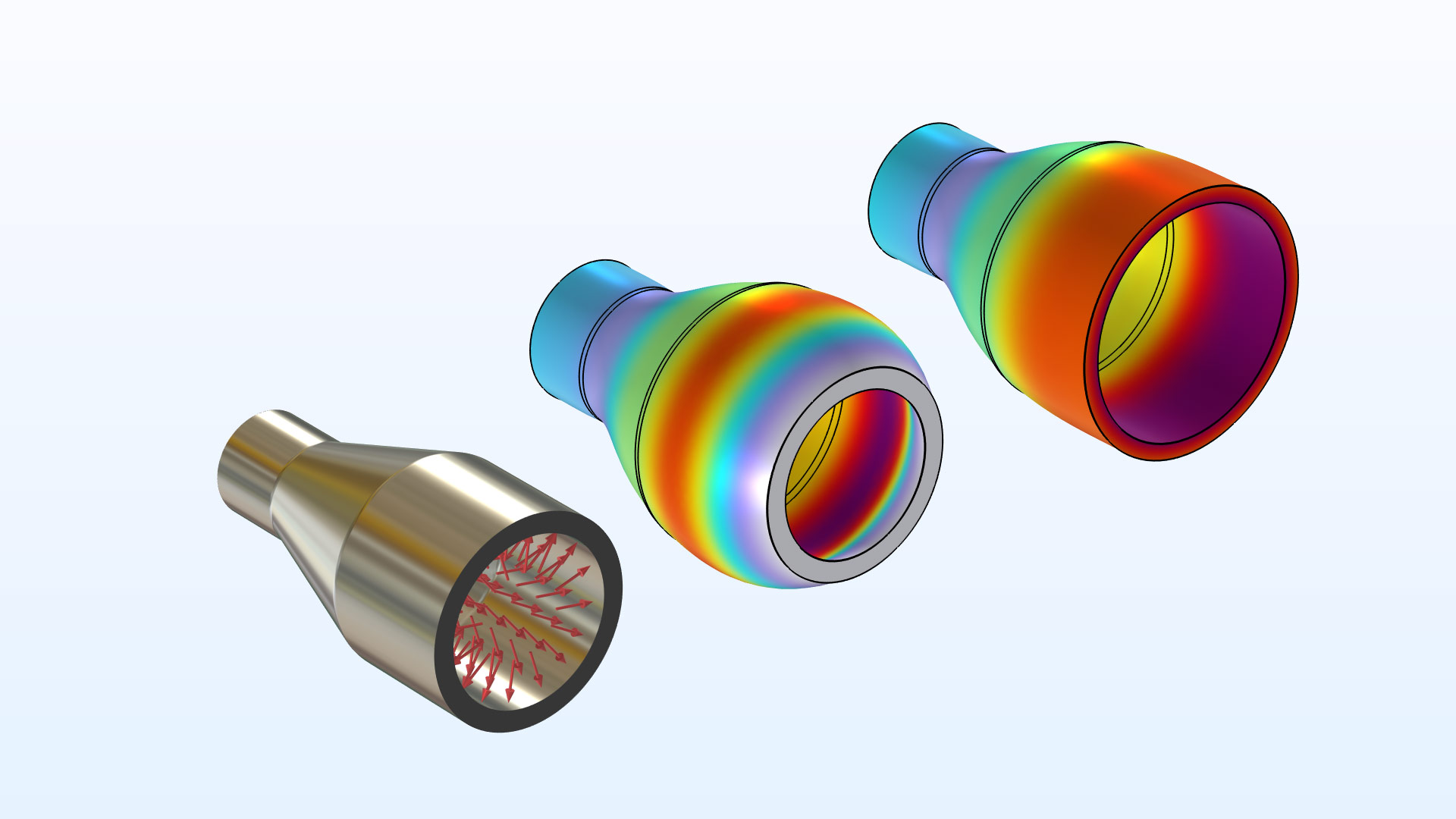
For boundary loads and sets of point loads, you can now specify the total force and moment with respect to a given point by selecting the Resultant option from the Load type list. This makes it easier to apply load resultants without either imposing artificial constraints or making long calculations of the actual load distributions. It is possible to control the assumed shape of the load distribution.
A bending load given as a moment resultant is applied to the end of a beam, modeled as a 3D solid. The actual load distribution is shown by arrows.
New Inputs for Anisotropic Materials
For the Linear Elastic Material feature, several new options for entering elastic constants have been added:
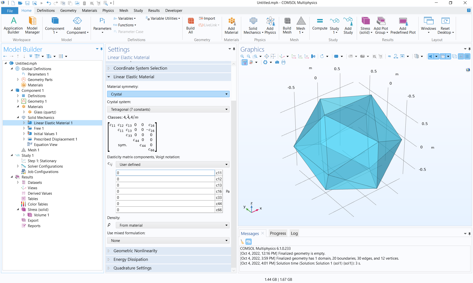
- Orthotropic materials can now be described by crystal data for seven different types of crystal systems: cubic, hexagonal, trigonal with six constants, trigonal with seven constants, tetragonal with six constants, tetragonal with seven constants, and orthorhombic.
- Input for transversely isotropic materials is supported, reducing the number of inputs for this class of materials.
- A general anisotropic material can now, in addition to the elasticity matrix, be represented by its compliance matrix.
Improvements for Rigid Connectors
The Rigid Connector is an important tool for abstract modeling, such as when applying loads and connecting objects. Its functionality has been augmented in three respects:
- It is now possible to disconnect selected degrees of freedom, such as in directions given by a local coordinate system. With this option, it is possible to release excessive constraints and reduce local stress concentrations.
- For two-point rigid connectors in 3D, it is possible to automatically suppress the potential rotational singularity.
- As a new default, the degrees of freedom that are generated by rigid connectors are now grouped together in the study sequence. This can dramatically reduce the number of nodes in the model tree and makes it easier to apply manual scaling for the convergence tolerance. The same change also applies to the Attachment feature.
Results in Local Coordinate Systems
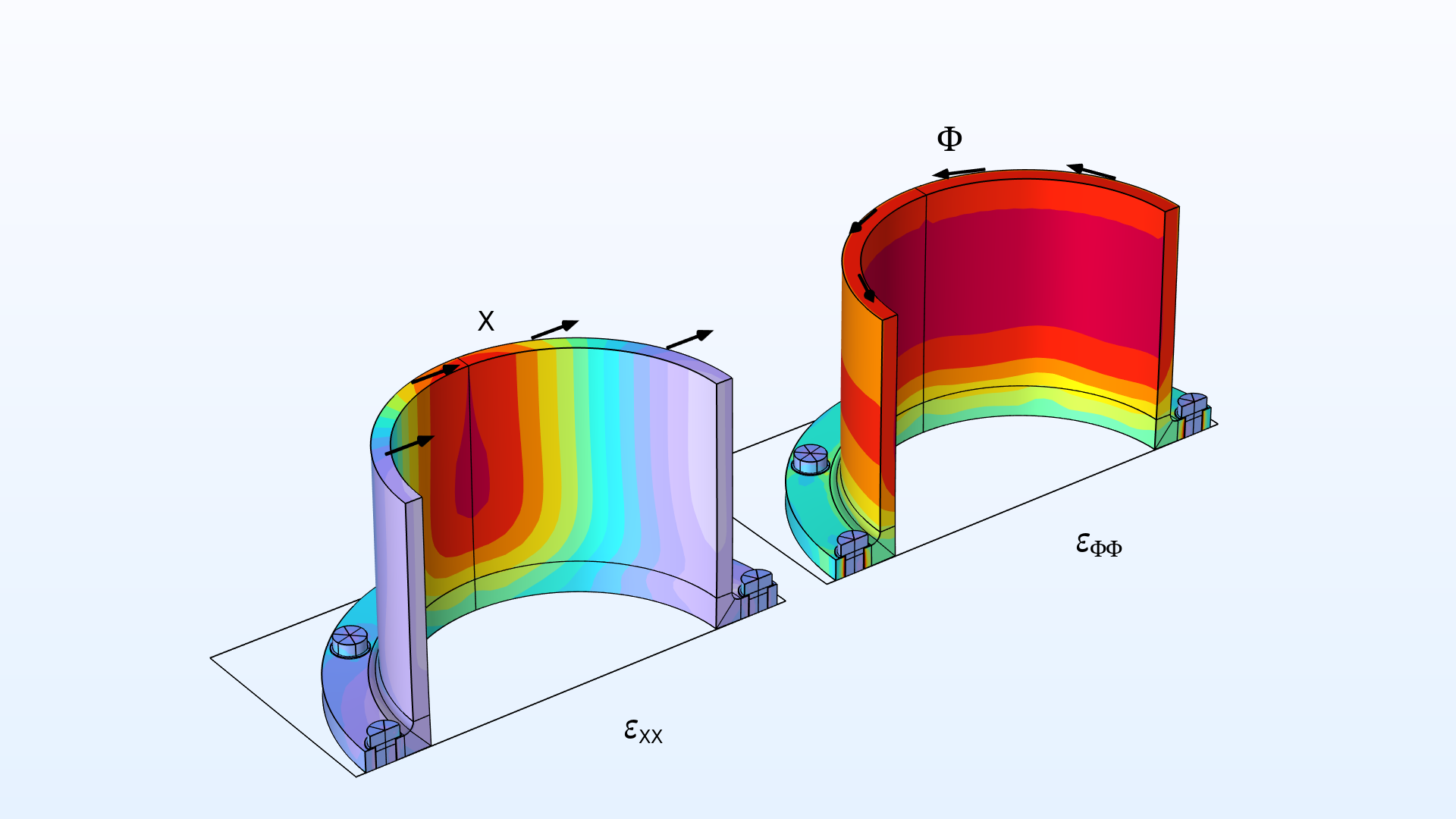
It is now easy to define an arbitrary number of local coordinate systems by adding Local System Results nodes for the evaluation of common quantities in the Structural Mechanics interfaces. Among the available transformed quantities, you will find stresses, strains, displacements, and material properties.
Fracture Boundary Condition for Elastic Waves
The new Fracture boundary condition, available in the Elastic Waves, Time Explicit physics interface, is used to treat two elastic domains with imperfect bonding. The fracture can be a thin elastic layer, fluid-filled layer, or discontinuity in elastic materials (an interior boundary). Several options exist for specifying the properties of the thin elastic domain. Typical applications are for modeling nondestructive testing (NDT) applications, such as inspecting the response of delamination regions or other defects, or for modeling wave propagation in fractured solid media in the oil and gas industry.
Predefined Plots
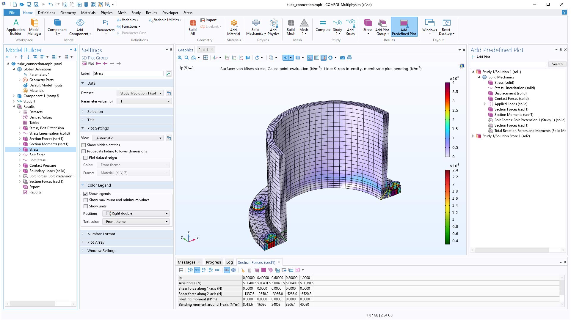
General functionality for predefined plots has brought extensive updates to the Structural Mechanics interfaces. A predefined plot is similar to a default plot, but with the important difference that it is not added to the Model Builder until the user selects to do so. This is advantageous because the number of default plots that are generated for each study has been decreased significantly.
In addition, users will see the following two improvements:
- Several new useful plots are now available from the Add Predefined Plot menu, in addition to the default plots in previous versions.
- Result plots for intermediate study steps — for example the loading step in a prestressed dynamic analysis — are directly available.

