support@comsol.com
Mesh Updates
COMSOL Multiphysics® version 6.1 provides significant meshing improvements that make it easier and more efficient to clean up and repair meshes, generate better-quality boundary layer meshes, and combine geometry models with imported meshes. Browse all of the mesh updates below.
New Operations for Cleanup and Repair
In this version, you can now use a Merge Entities operation to merge nearby vertices, edges, and surfaces within a specified tolerance in a mesh. It is now possible to merge boundaries of misaligned parts in a CAD assembly to eliminate gaps, for example. This provides an alternative to traditional CAD defeaturing and repair.
Merging the intersecting boundaries in this mesh repairs the misalignment and connects the two parts of the CAD assembly.
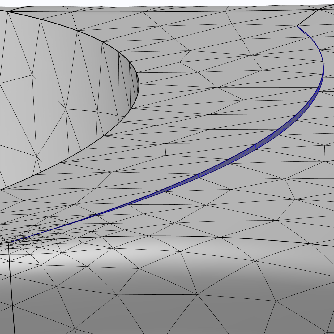
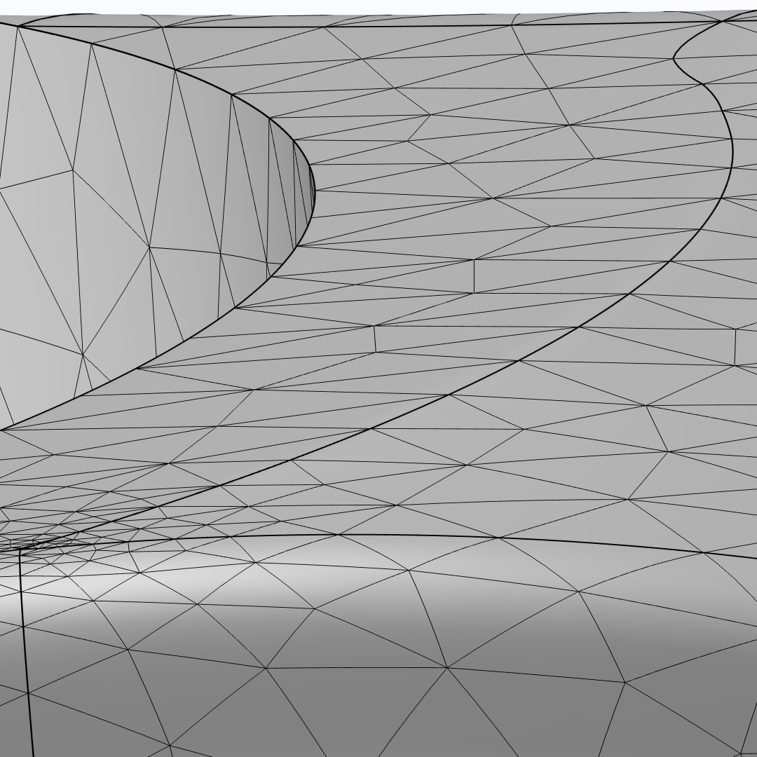
Similarly, you can use the Collapse Entities operation to clean up a mesh by collapsing narrow and small faces and short edges. The operation finds and collapses entities smaller than the automatically determined entity size. If you do not want to use the default size, you can instead manually specify a size. With this option, the entities will still be automatically collapsed if they do not meet the size requirements.
Collapsing a sliver boundary (left) into an edge (right).
Boundary Layer Meshing Improvements
There is a new Maximum angle for trimming setting for boundary layer mesh generation that controls whether to trim the boundary layer mesh in narrow corners. This setting is now available for all options for handling sharp edges. You can see this improvement in the existing Nonisothermal PEM Fuel Cell model.
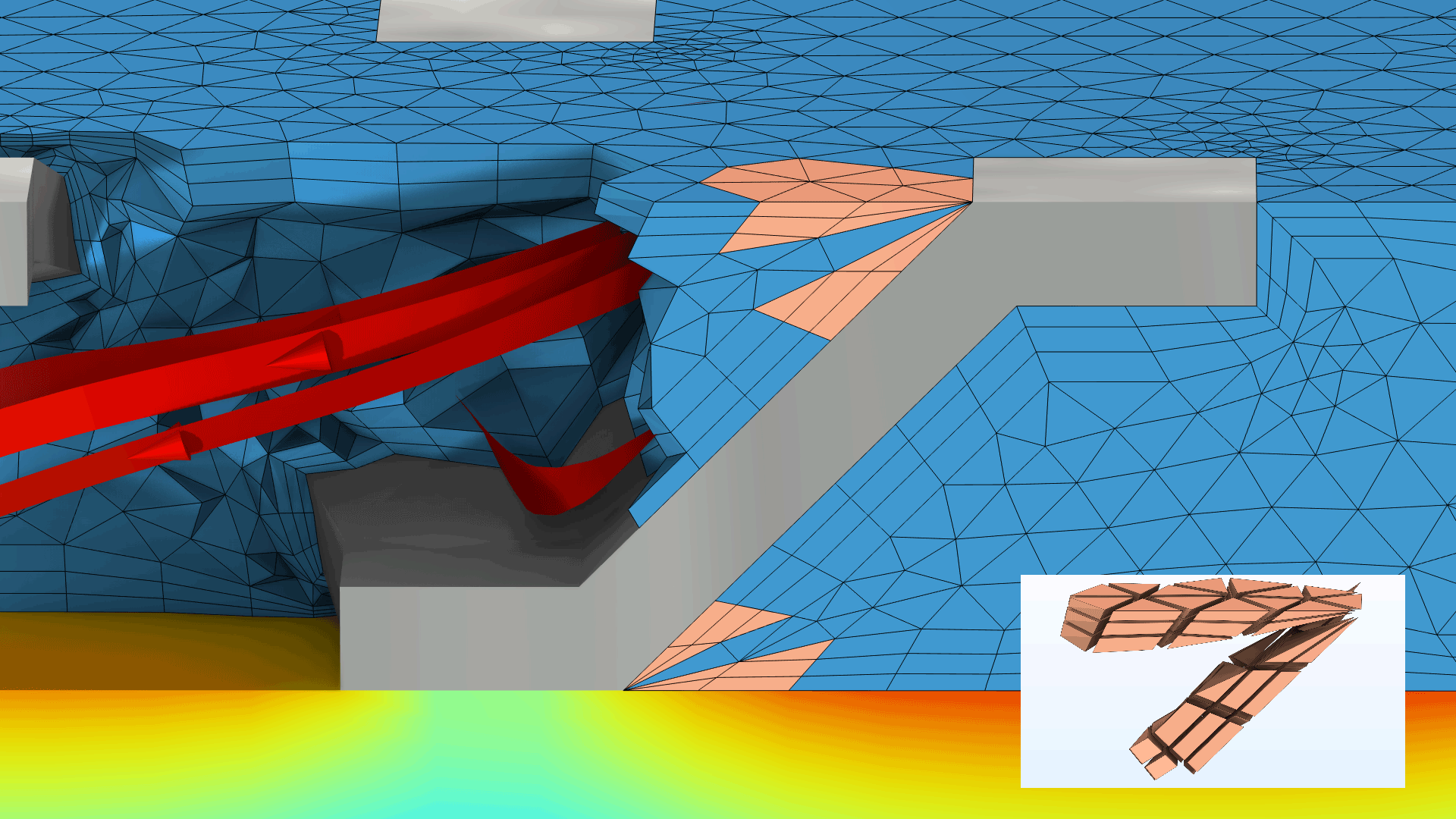
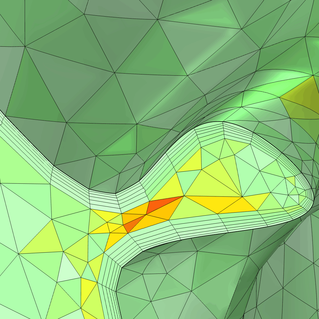
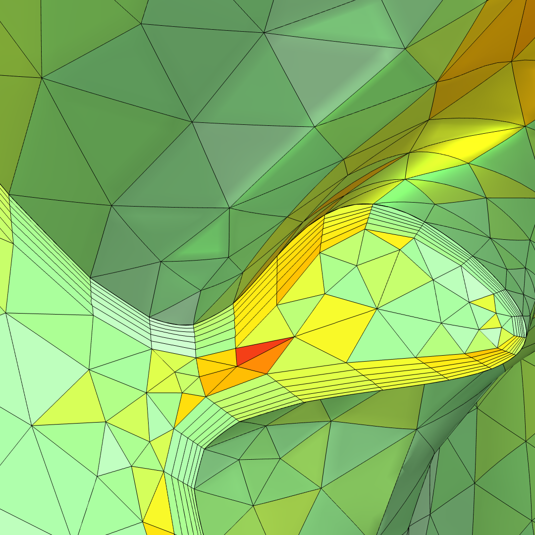
In the settings for the Boundary Layer Properties node, a new Adjust directions for each layer check box is available that enables smoothing of the directions in boundary layer elements and makes it possible to generate boundary layer meshes of higher quality. The direction of the first layer is perpendicular to the surface (left image below), which is often desired when solving fluid flow problems. After the first layer, the directions of the next layers are able to change to concave- and convex-shaped boundaries. The previous default option of generating layers with constant directions (right image below) is also available.
Boundary layers with adjusted layer directions (left) and with constant layer directions (right). The light green colors represent high element quality.
Combining Geometry and Mesh
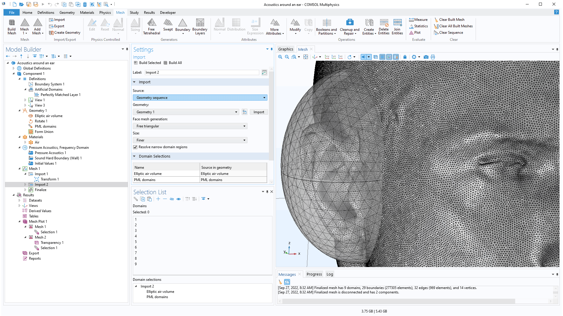
The Import operation now makes it easier to combine a geometry model with an imported mesh. This works by importing the finalized geometry of the geometry sequence directly into a meshing sequence. The import generates an unstructured triangular mesh or a visualization mesh for the geometry. The named selections are automatically transferred and can be used in the meshing sequence and for defining the physics. You can see this new improvement in the existing STL Import Tutorial Series model.
Improvements for Named Selections in Meshes
The mesh operations now support named selections as input, even when working with imported meshes. The named selections can either be imported from a mesh file or with the geometry from a geometry sequence. You can use the named selections when, for example, remeshing boundaries after combining geometry with an imported mesh. View this update in the STL Import Tutorial Series model.
Mapped and Swept Meshing for Imported Meshes
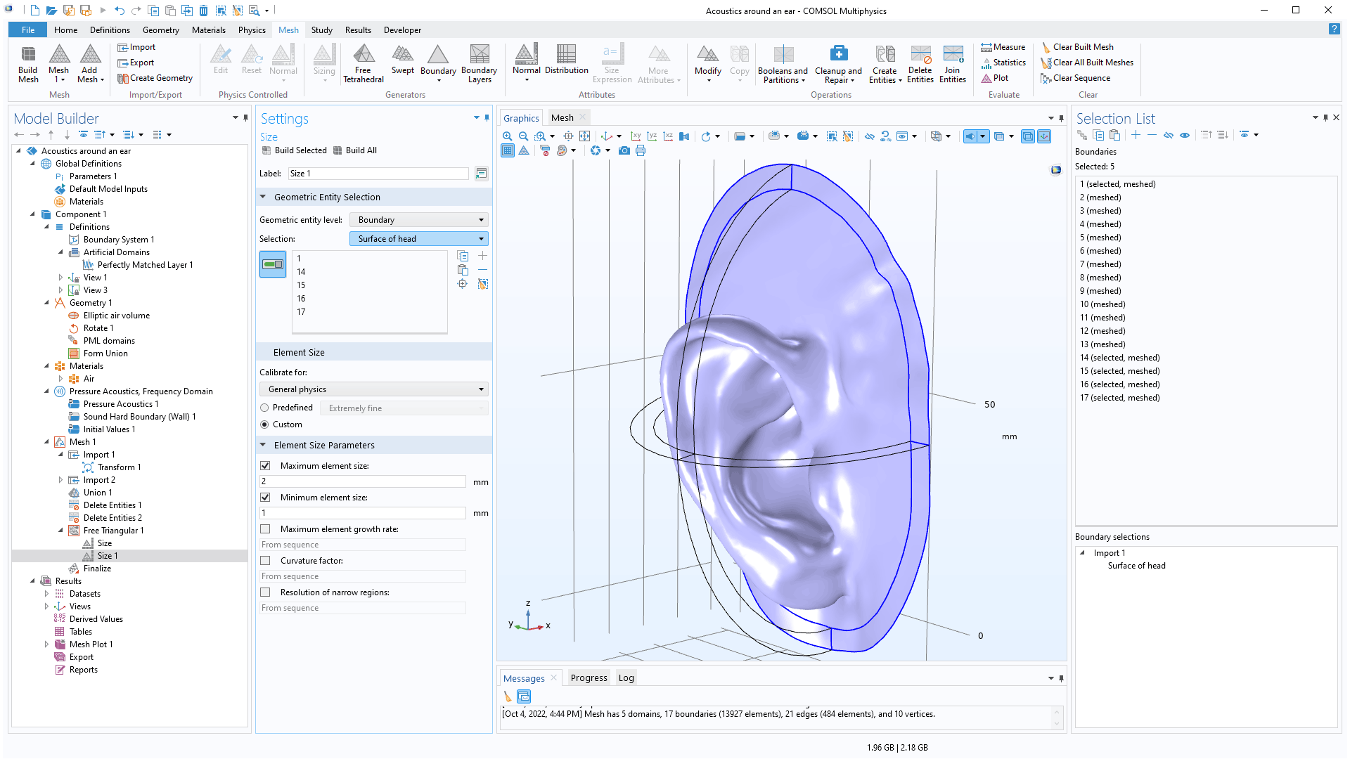
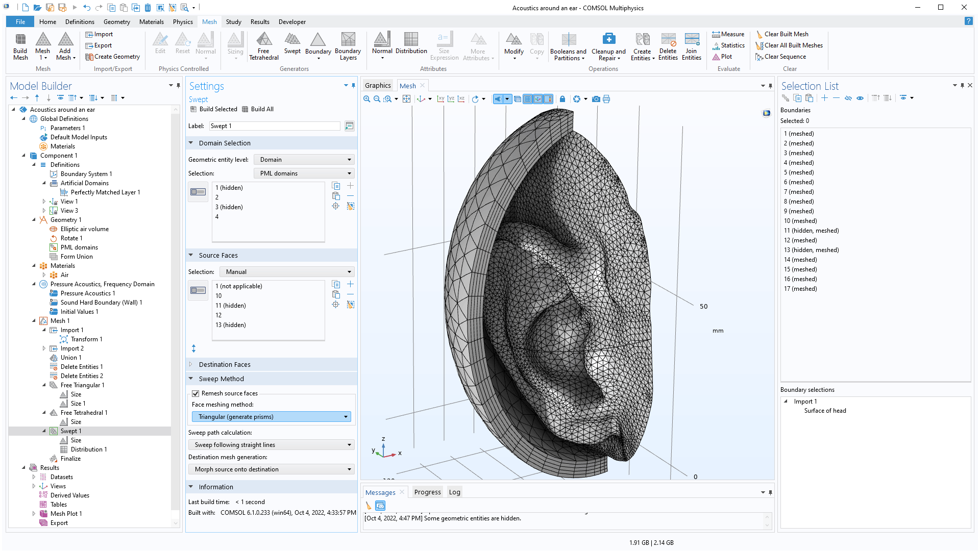
In version 6.1, generating meshes with the Mapped and Swept operations is now straightforward for all meshes, including imported meshes. The Swept operation has support for remeshing the source faces using a quadrilateral or triangular mesh. In previous versions, you had to create a geometry from the imported mesh to be able to generate a mapped or swept mesh. The new workflow is significantly more robust and efficient.
Improved Workflow for Imported Surface Meshes
When importing meshes from the STL, PLY, and 3MF formats, domains are now automatically created in watertight regions using the new Create domains check box. If there are holes in the mesh, boundaries and edges are reported in Information nodes, which can be used as input for the Fill Holes and Create Faces repair operations. The domains will be created when the holes have been repaired and the surface mesh has formed the watertight regions. In previous versions, creating domains required an additional operation. The STL Import Tutorial Series model showcases this new addition.
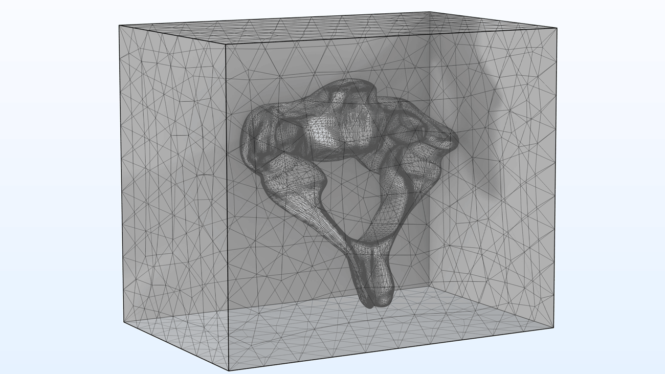
The imported STL mesh of a vertebra with two small holes is repaired using the Fill Holes repair operation that automatically creates a computational domain.
Updated Tutorial Model
COMSOL Multiphysics® version 6.1 includes an updated meshing tutorial model.
STL Import 2 — Remeshing an Imported Mesh
Application Library Title:
stl_vertebra_mesh_import
Download from the Application Gallery

