Plasma Module Updates
For users of the Plasma Module, COMSOL Multiphysics® version 5.3a brings a new physics interface for modeling capacitively coupled plasmas orders of magnitude faster than before, with several new features and tutorials included to demonstrate the functionality. Learn about these plasma updates below.
New Physics Interface for Modeling Capacitively Coupled Plasmas
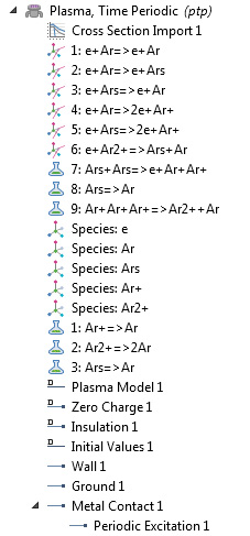
The new Plasma, Time Periodic physics interface has been added for modeling capacitively coupled plasmas (CCP) with significantly faster computation times. Instead of solving the problem in the time domain, the periodic steady-state solution is computed with a new approach. The physics interface attaches an extra dimension to the underlying mathematical equations representing one RF cycle and enforces periodic boundary conditions in the aforementioned extra dimension. This avoids having to solve for tens or hundreds of thousands of RF cycles, which typically takes a long time before the plasma reaches the periodic steady-state solution. This novel approach maintains all the nonlinearity of the model while dramatically reducing computation time: 1D models take seconds to solve and 2D models typically take on the order of an hour for a given power input. Compared to solving the problem in the time domain with COMSOL Multiphysics®, the following speedup is observed (assuming 50,000 RF cycles before the discharge reaches its periodic steady-state solution).
| Dimension | Approximate Time (Version 5.3) | Approximate Time (Version 5.3a) |
|---|---|---|
| 1D | 10 hours | 20 seconds |
| 2D | 2 weeks | 1 hour |
Additionally, this new modeling approach has the following advantages:
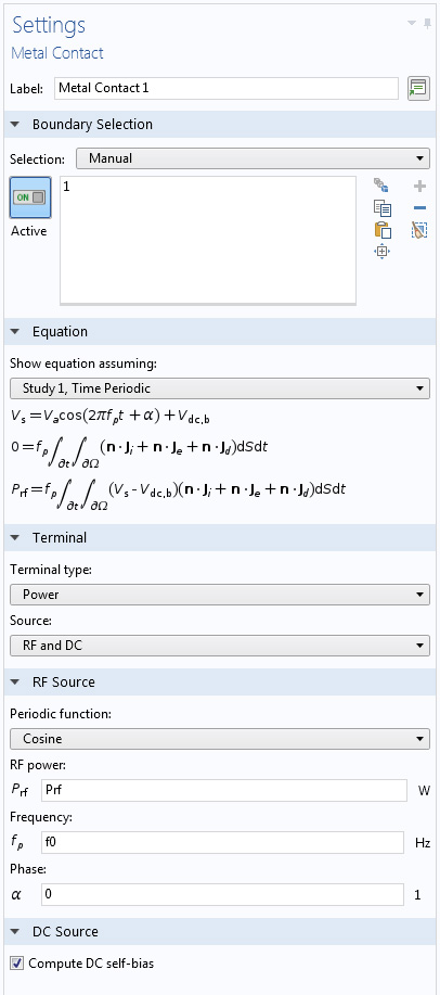
- Integrals performed over both the extra dimension and the base geometry can be used in the equations themselves. This allows the contacts and terminals to be driven directly with a fixed power rather than a fixed voltage, which is important not only for numerical stability but also for discharges where an alpha-to-gamma transition occurs. In these cases, a given voltage excitation could produce two different solutions depending on the initial conditions; but with a fixed power, only one physical solution exists. Also, the discharge power is usually known, whereas the electrode potential is often not.
- The DC self-bias can be computed easily with an additional equation, rather than the ad hoc methods used in traditional methods.
- Parametric sweeps over the operating conditions are fast and easy, since the problem is not solved in the time domain. For 1D models, a range of powers, pressures, frequencies, etc. can be swept in only a few minutes.
- Matching networks are more easily included in the model, so the plasma can be driven from an L-type matching network. Additionally, it is easy to compute the plasma impedance at the fundamental frequency, which is useful when designing matching networks.
- The harmonics generated by the plasma are still resolved by the method; there are no approximations in the model. It is possible to observe how these harmonics in the discharge current can lead to an impedance mismatch when driving with an external circuit.
- The method is well suited for a modern computer architecture, since reassembling and paging in and out of memory at each time step is not necessary. Nearly all the time is spent performing the factorization of a sparse matrix with a direct solver, which is highly parallelized and runs at a very high FLOPS rate.

The Argon GEC CCP Reactor, 2D model uses the new Plasma, Time Periodic interface, with the period-averaged electron density shown here.
New Features with the Plasma, Time Periodic Interface
Electrical Excitation
While modeling in the new Plasma, Time Periodic interface, electrodes can be driven with either a fixed voltage or a fixed power from a Metal Contact or Terminal boundary condition. Additionally, an arbitrary number of applied frequencies can be included in the model, and the power or voltage for each frequency can be specified independently. Electrodes can also be driven by an external circuit; a parallel RC circuit, an L-network, or a reversed L-network.
Secondary Emission
Secondary emission can now be included via direct reemission of secondary electrons due to an incident ion flux on a surface or by using an approximate, or uniform, model for secondary electrons that exhibit beaming effects. Electrons that exhibit beaming effects typically occur for discharges that are at low pressures and high powers.
To enable this functionality, you must click the Show button in the Model Builder toolbar and then select Advanced Physics Options. In the Plasma, Time Periodic node, a Secondary Emission Model section will appear, where you can select between From surfaces (default) or Uniform (new in version 5.3a of the COMSOL Multiphysics® software). When the Uniform option is selected, you can define the Characteristic gap size and Beam energy for the secondary emission model.
Ion Energy Distribution Function
Often the quantity of interest when modeling capacitively coupled plasmas, you can now compute the ion energy distribution function (IEDF) and ion angular energy distribution function (IAEDF) by combining your plasma solution with the Particle Tracing Module.
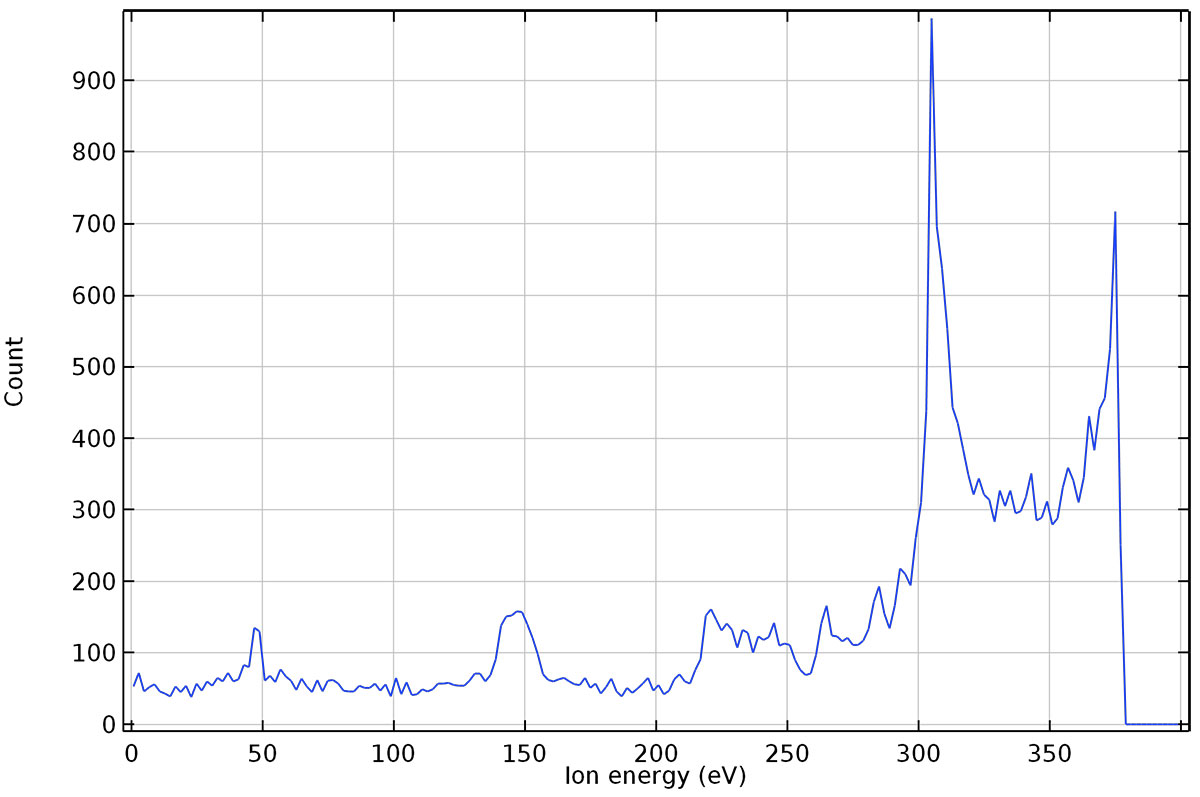
An IEDF showing the classical double peak in energy, with a midpoint corresponding to the sum of the DC self-bias and plasma potential. The low-energy part of the IEDF also has several well-defined peaks.
New Tutorial Model: Argon GEC CCP Reactor, 2D
The National Institute of Standards and Technology (NIST) Gaseous Electronics Conference (GEC) CCP reactor provides a standardized platform for studying capacitively coupled plasmas. Even the simplest plasma models are quite involved, so a 2D example helps in understanding the physics without excessive CPU time. Using the new Plasma, Time Periodic physics interface, the periodic steady-state solution of an argon discharge is computed with good agreement when compared with measurements and simulations in the literature.
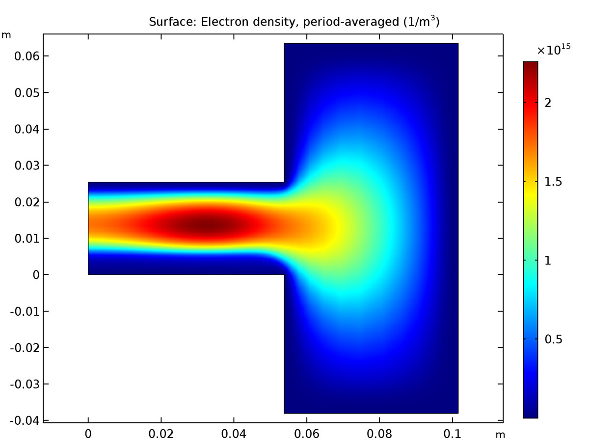
Period-averaged electron density (1/m3) inside the GEC reactor for 1 W of power deposition. The calculated densities agree well with those published in the literature.
Animation of the power deposition (W/m3) inside the GEC reactor.
Animation of the electron density (1/m3) inside the GEC reactor.
Animation of the electric potential (V) inside the GEC reactor.
Application Library path:
Plasma_Module/Capacitively_Coupled_Plasmas/argon_gec_ccp
New Tutorial Model: Alpha to Gamma Transition
Capacitively coupled RF discharges can operate in two distinct regimes depending on the discharge power. In the low power regime, known as the α regime, the electric field oscillations heat and create electrons. In the high power regime, known as the γ regime, the discharge is sustained primarily by electron avalanche within the plasma sheath. This is initiated by secondary electrons emitted due to ion bombardment of the electrodes. The two regimes present fundamental differences that can have an important impact in plasma applications.
In this model, the new Plasma, Time Periodic physics interface is used to model the two regimes and the transition between them. Results are presented for the electron creation and power absorbed by the electrons that illustrate the main features of the two regimes. That is, a low power region, where larger voltage amplitudes are needed to increase the power absorbed by the discharge, and a high power region, where high discharge powers are attained for progressively lower voltage amplitudes.
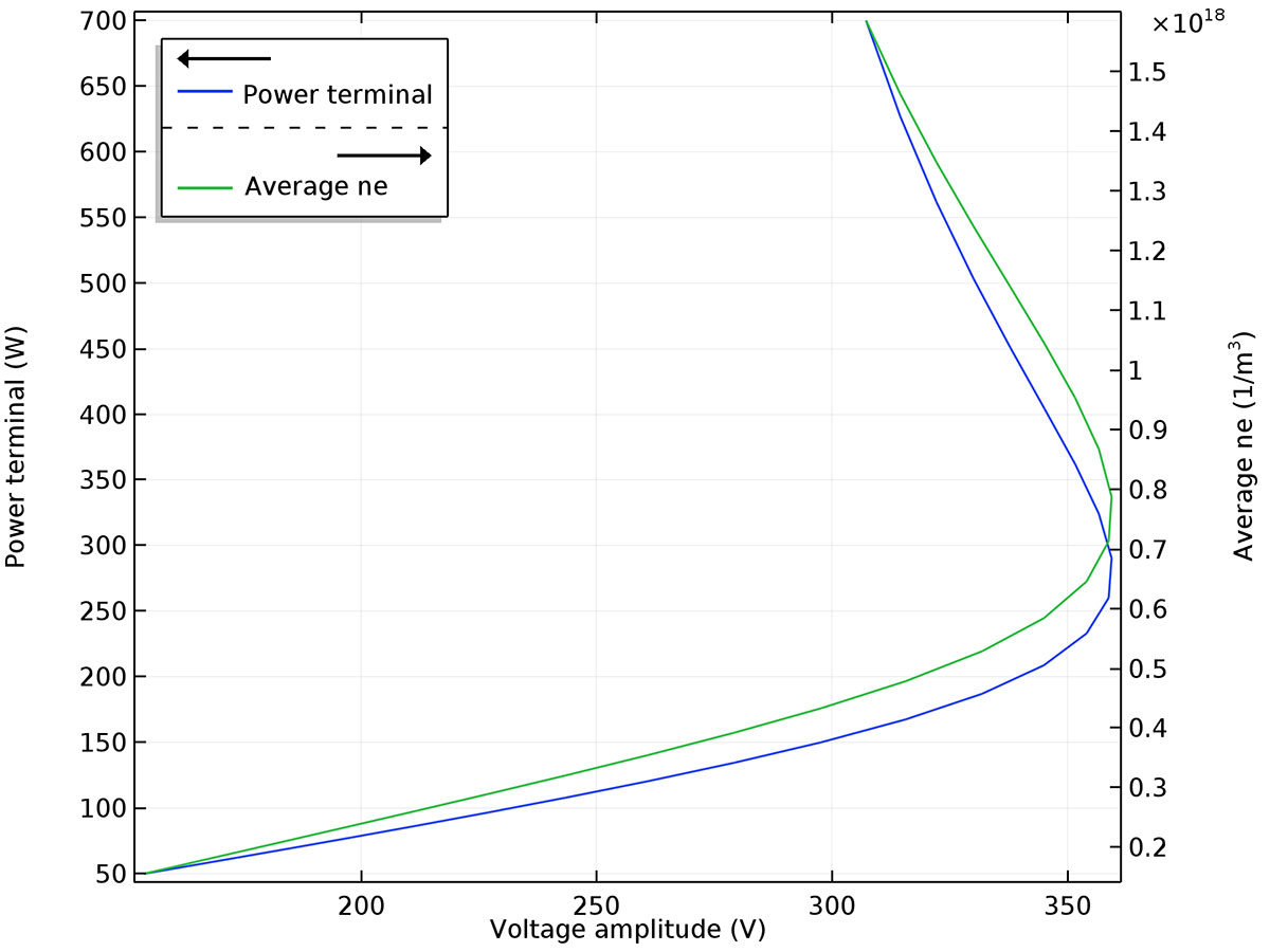
The power absorbed by the plasma and the averaged electron density as a function of the voltage amplitude. It is possible to identify the low power region and the high power region, described in the text above.
Application Library path:
Plasma_Module/Capacitively_Coupled_Plasmas/alpha_to_gamma_transition
New Tutorial Model: Computing the Ion Energy Distribution Function in a 2D CCP Reactor
Plasma processing techniques are widely used in industry to modify the chemical and physical properties of surfaces. Some processes require energetic ion bombardment and a high degree of ion velocity anisotropy. Therefore, it is of great value to know the IEDF and the velocity dispersion at the surface. In this tutorial model, the IEDF at the electrode surface is computed for a commercial CCP reactor. The computed IEDF is compared with experimental measurements and reasonable agreement is found.
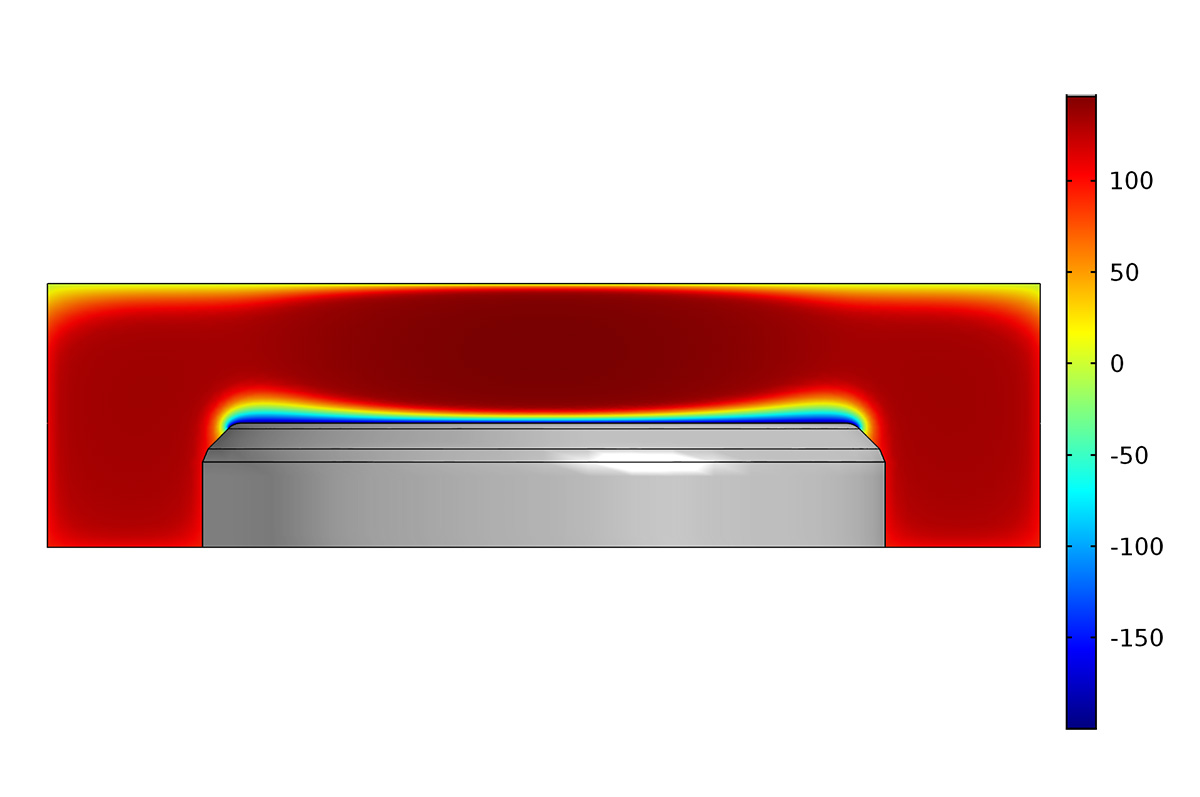
Surface plot of the period-averaged electric potential (V) in a commercial CCP reactor. The reactor is asymmetric leading to a negative DC self-bias on the powered electrode.
Application Library path:
Plasma_Module/Capacitively_Coupled_Plasmas/ccp_ion_energy_distribution_function
New Tutorial Model: Computing the Plasma Impedance
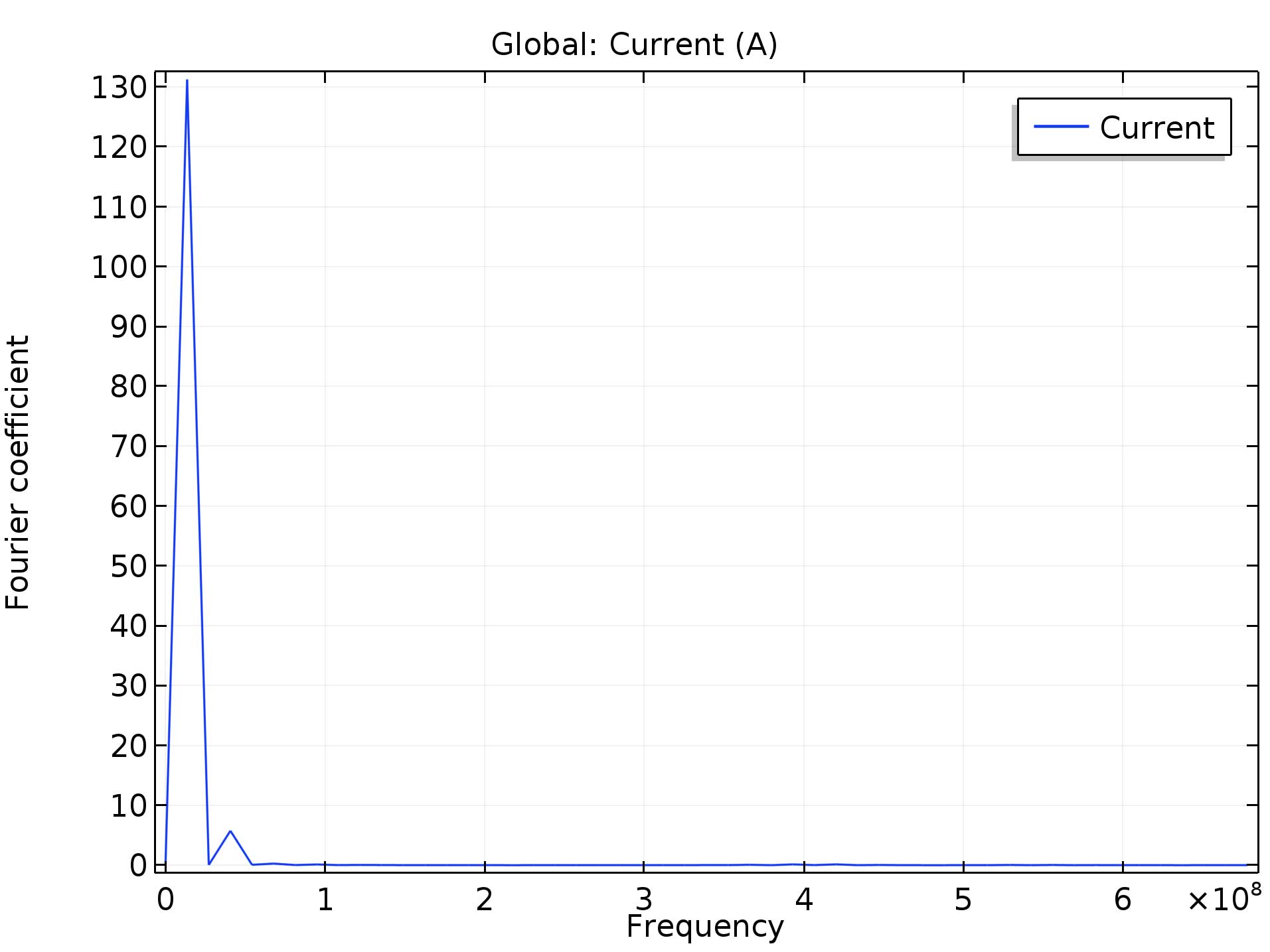
This tutorial model demonstrates how to compute the impedance of a capacitively coupled plasma, useful when designing matching networks. The Time Periodic study computes the time periodic solution of the plasma. Subsequently, the solution is transformed to the time domain, after which the fast Fourier transform (FFT) solver is called. This allows the plasma impedance to be computed for a given set of input parameters.
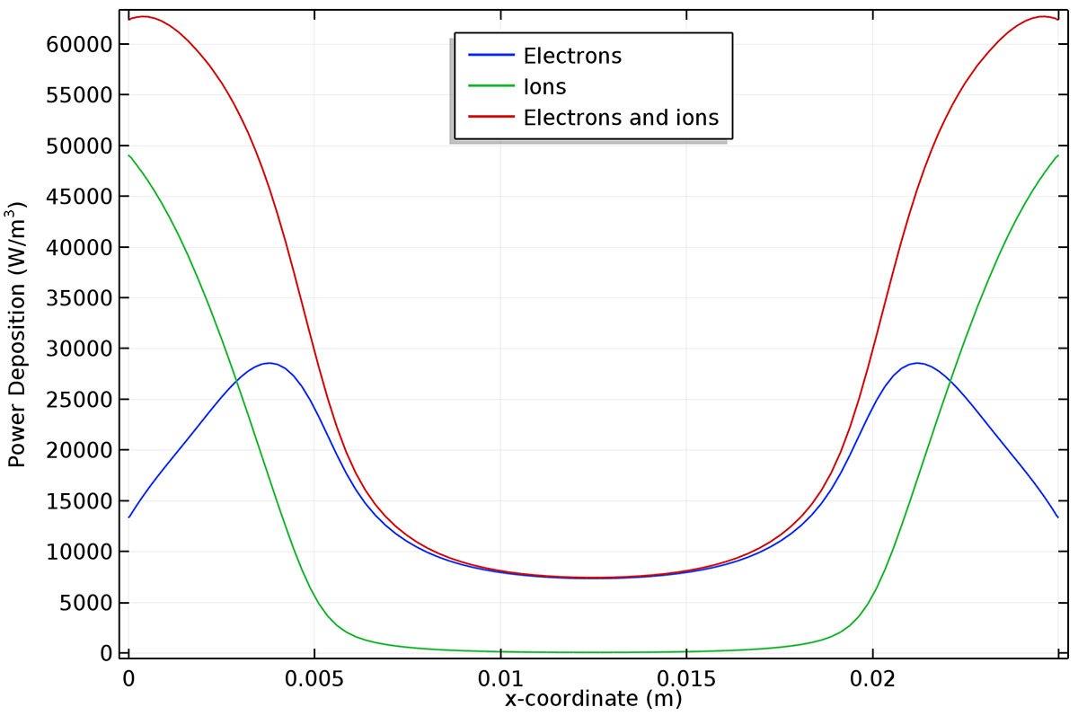
Period-averaged power deposition to the ions, electrons, and the sum of both. In the bulk, power absorption is dominated by the electrons, but in the plasma sheath it is dominated by the ions.
Application Library path:
Plasma_Module/Capacitively_Coupled_Plasmas/computing_plasma_impedance
New Tutorial Model: Impedance Matching
This tutorial model drives a capacitively coupled plasma with an L-type matching network at high and low powers. At low power, where the harmonics in the current are low, perfect matching is obtained at the chosen power value. Sweeps over power, frequency, and pressure are performed to examine their effect on the match power transfer ratio and efficiency. Finally, a sweep is performed over a higher power range, and the presence of sizable harmonics in the current causes an impedance mismatch.
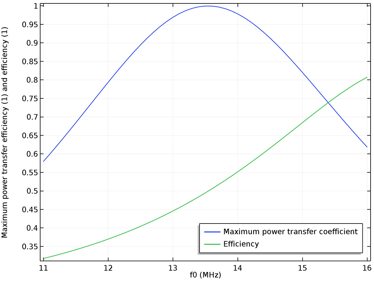
Plot of the maximum power transfer coefficient and efficiency as a function of the applied frequency. The L-match has been tuned for 13.56 MHz. As expected, the maximum power transfer coefficient is 1 at 13.56 MHz and the efficiency is exactly 0.5.
Application Library path:
Plasma_Module/Capacitively_Coupled_Plasmas/impedance_matching