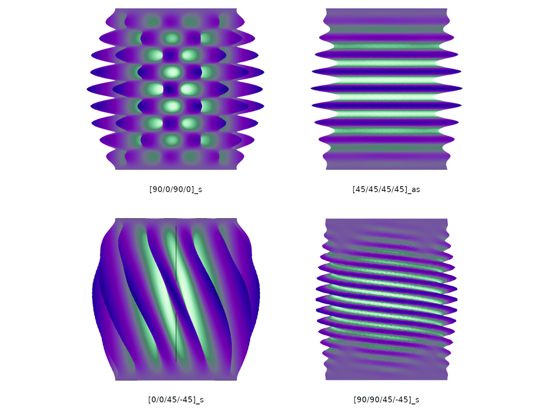
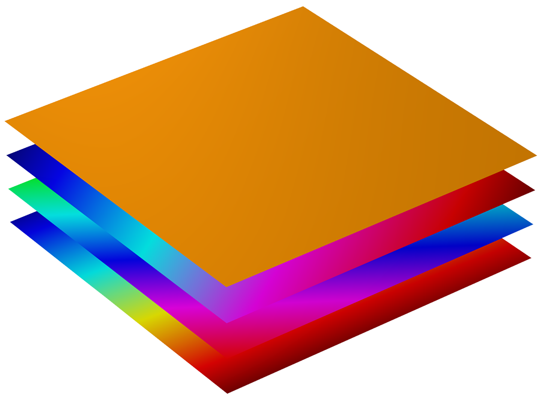
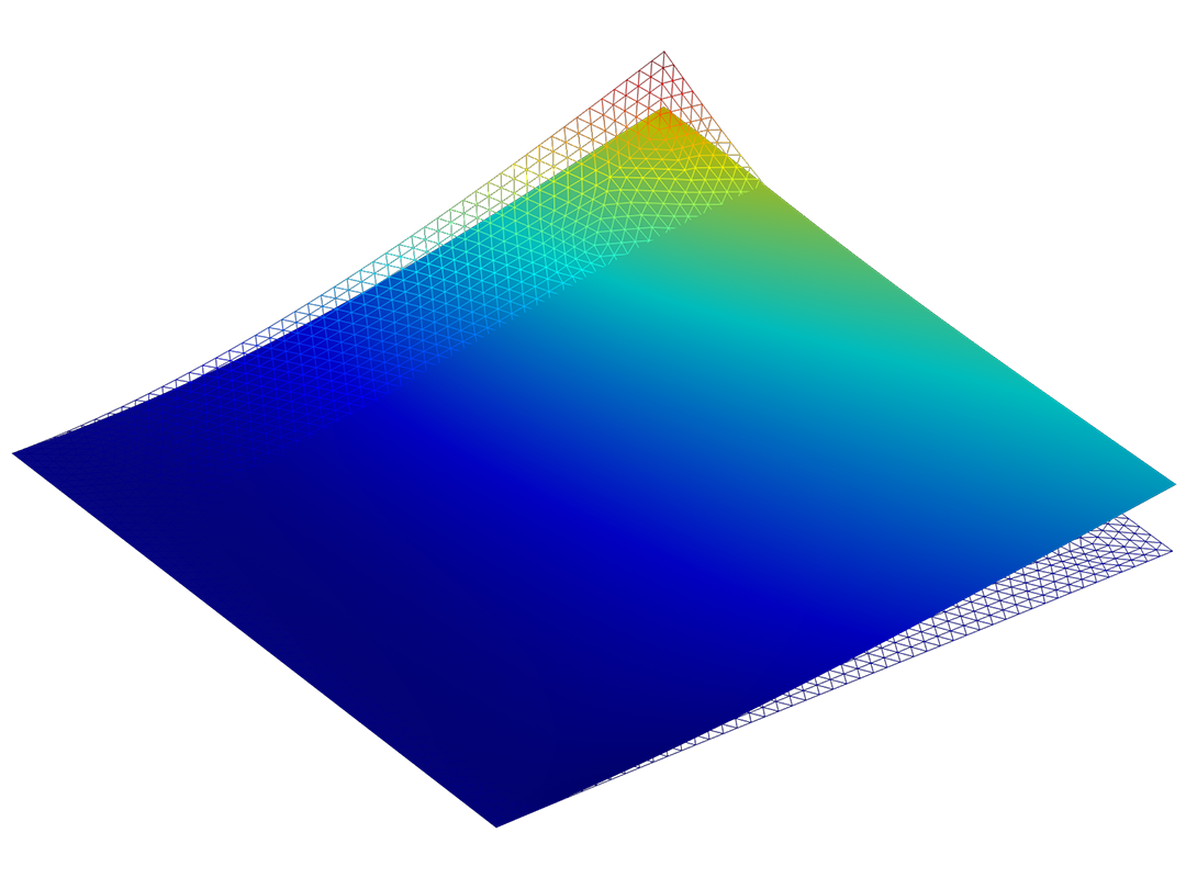
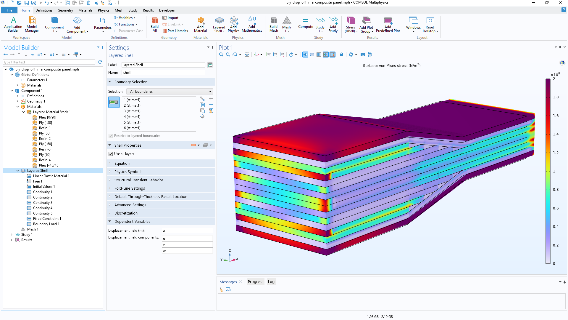
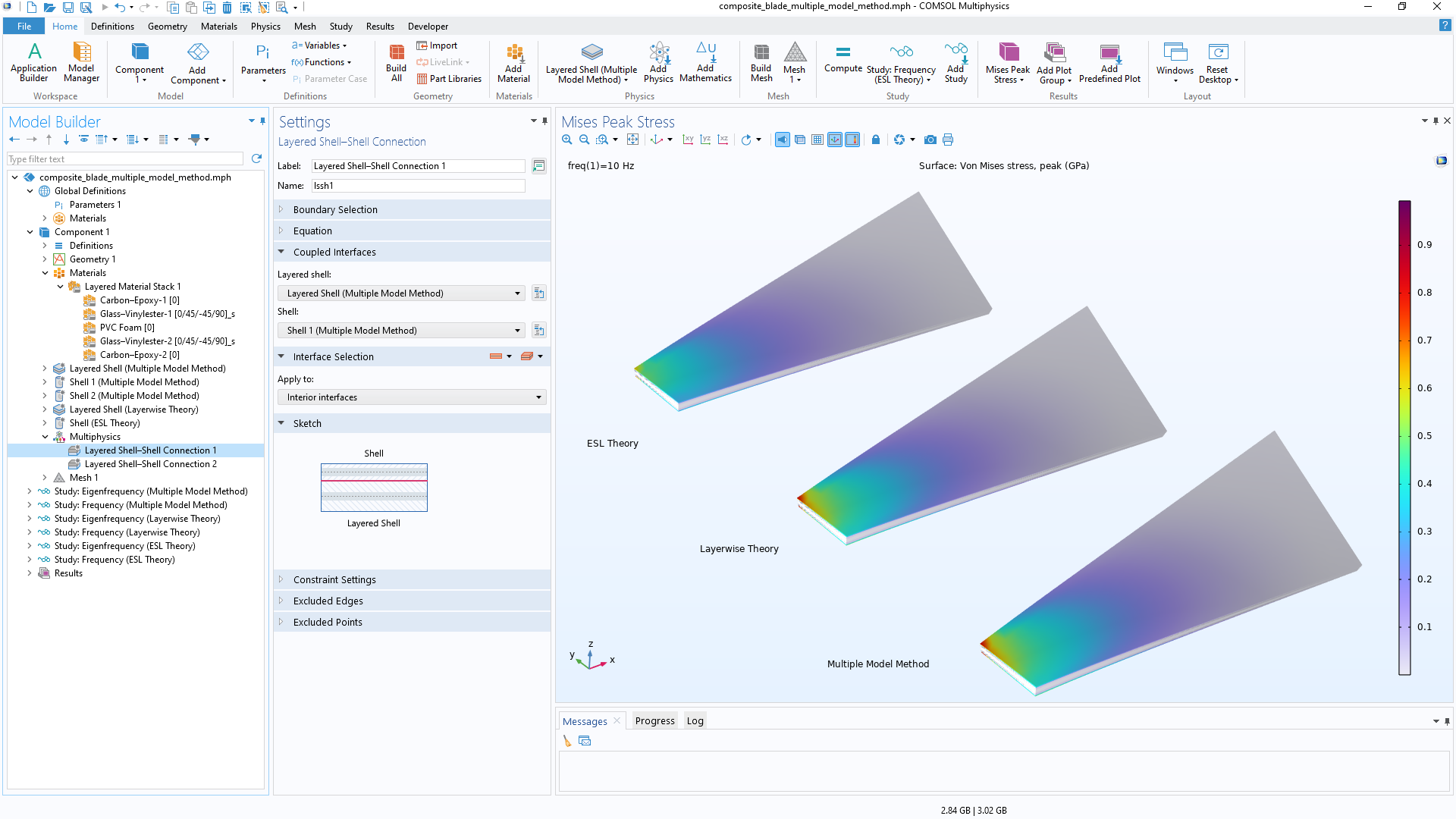
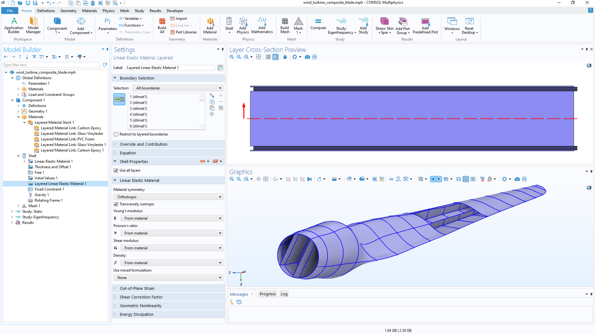
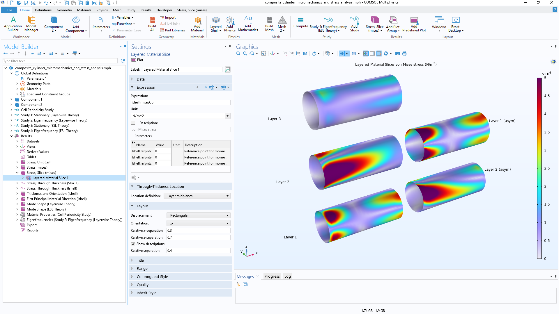
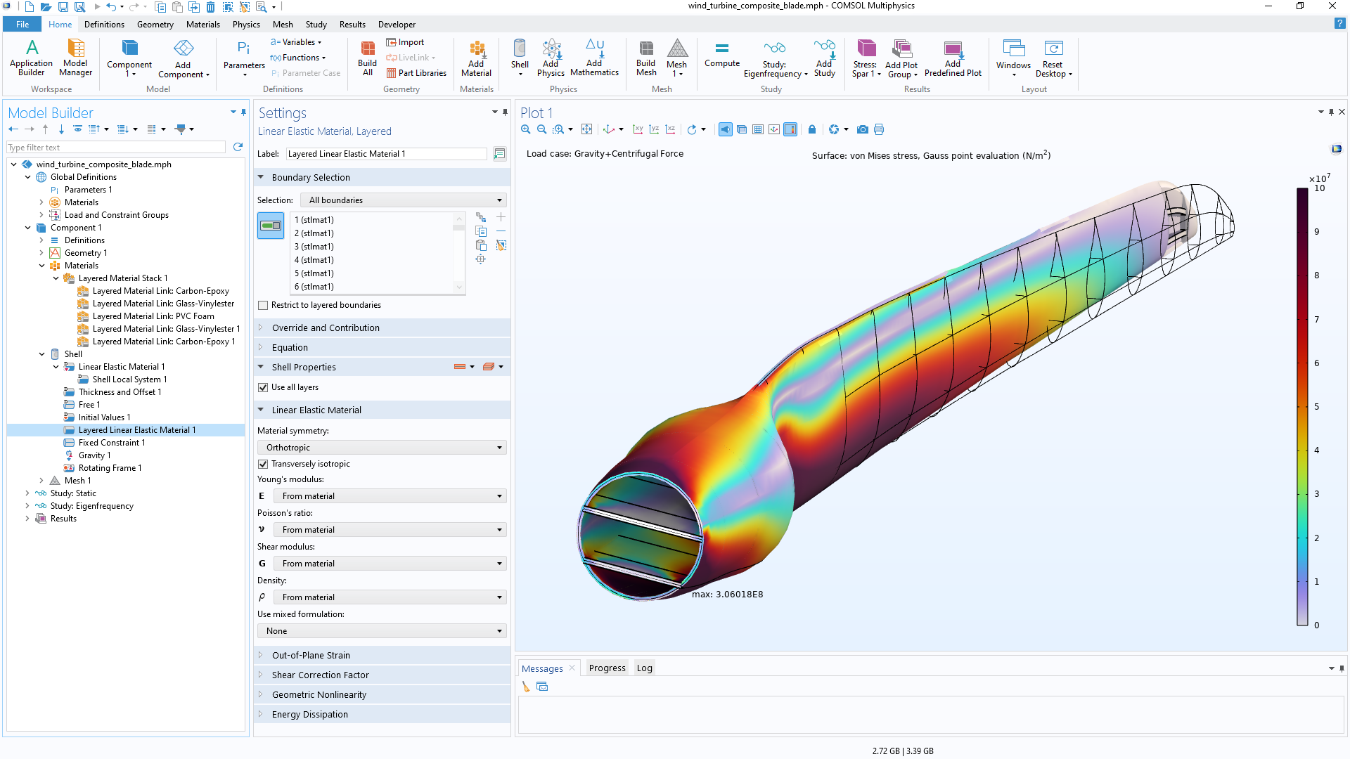
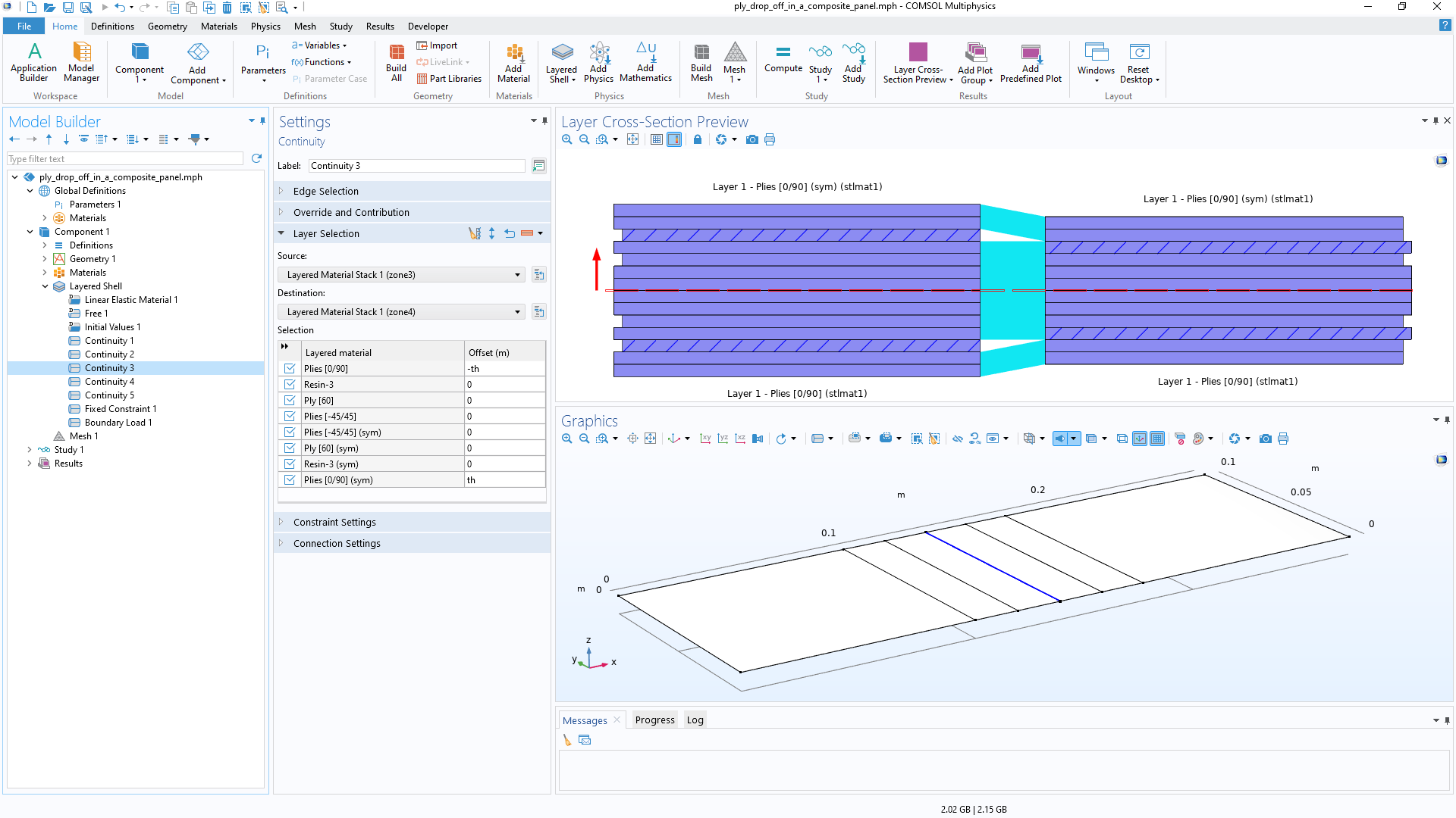
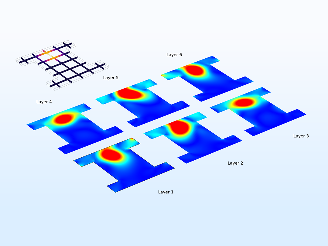
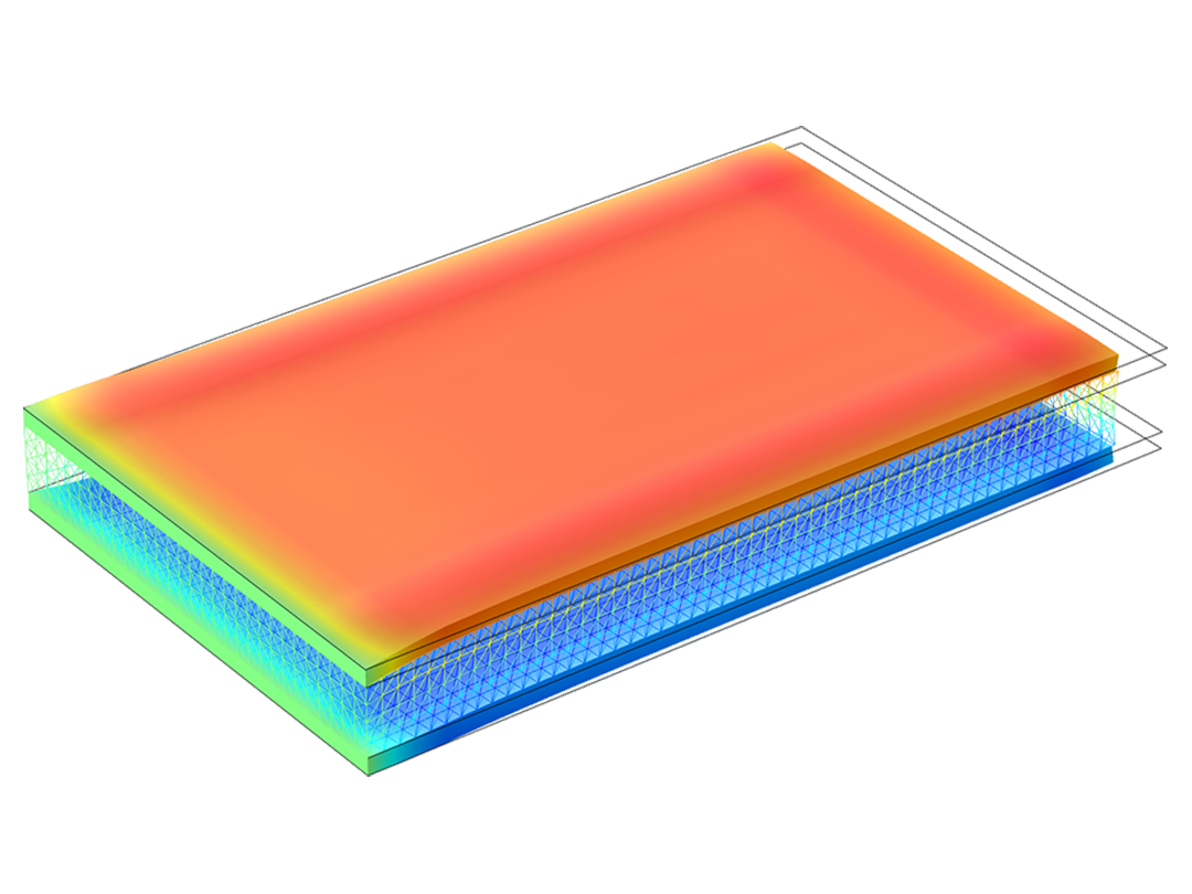
Composite Materials Module

Model Composite Structures for Improved Product Design

A composite material is a heterogeneous material composed of two or more integrated constituents for enhanced structural performance. The Composite Materials Module is an add-on to the Structural Mechanics Module that brings you modeling tools and functionality tailored for analyzing layered composite structures. Layered composite materials, such as fiber-reinforced plastic, laminated plates, and sandwich panels, are widely used in manufacturing aircraft components, spacecraft components, wind turbine blades, automobile components, buildings, boat hulls, bicycles, and safety equipment.

Additionally, when you combine the Composite Materials Module with other modules from the COMSOL product suite, you can extend your models to include heat transfer, electromagnetics, fluid flow, acoustics, and piezoelectric effects — all within the same simulation environment.

Contact COMSOL
Three wind turbine blades showing the stress on the skin (left), stress on the spars (middle), and the shell local coordinate system (right).

Laminate Theories to Define and Visualize Laminates

The analysis of laminated composite shells is commonly based on three-dimensional elasticity theory or equivalent single layer (ESL) theory.

The Composite Materials Module utilizes specialized layered material technology and provides two approaches that can be used to accurately model composite shells: layerwise theory and equivalent single layer theory. The layerwise approach is suitable for thick to moderately thin composite shells with a limited number of layers. The equivalent single layer theory is suitable for thin to moderately thick shells and can accommodate many layers without significant performance impact.
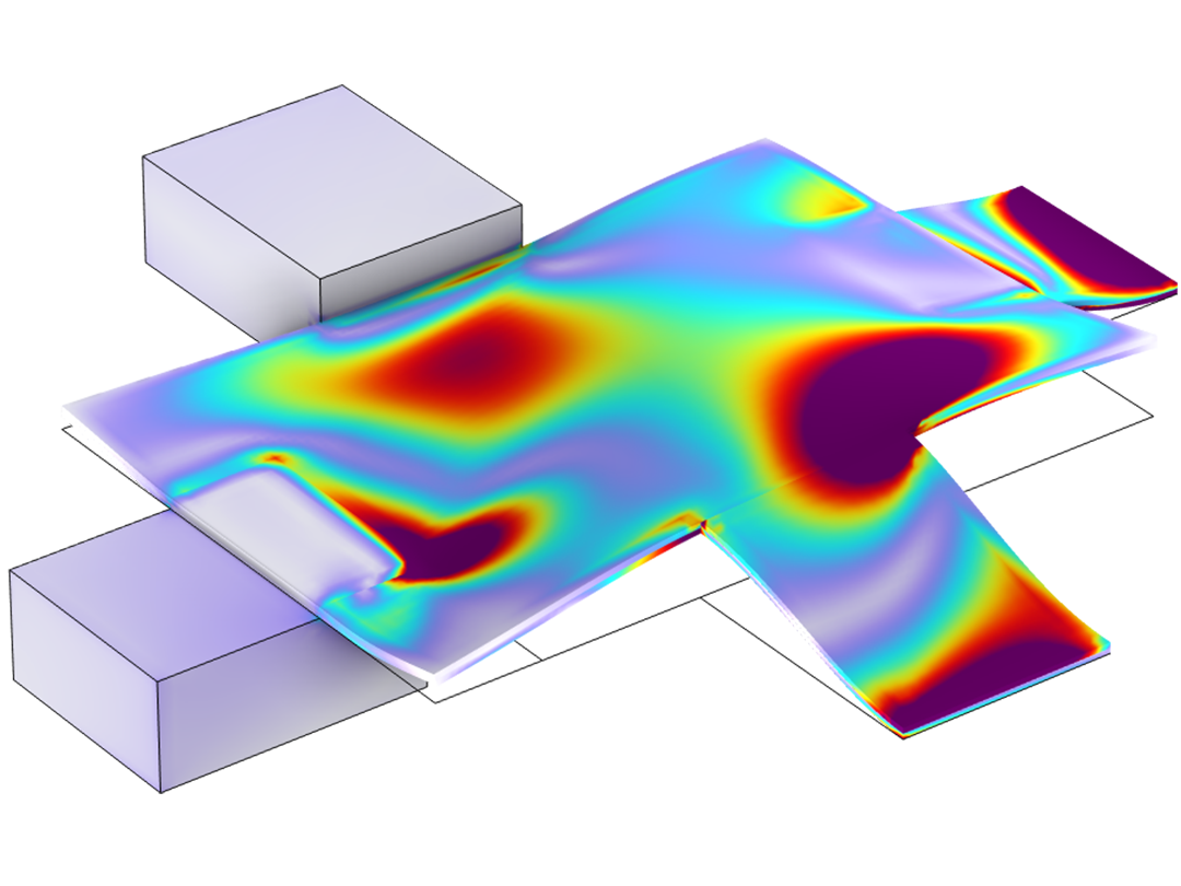
 Using these theories, you can optimize the layup and other parameters of a laminate by performing multiscale, multiphysics, and various failure analyses.

What You Can Model with the Composite Materials Module

Perform various structural analyses for composite laminates with the COMSOL® software.

A closeup view of a unit cell model with fiber and resin.

Micromechanical/Macromechanical

Compute homogenized material properties and macroscopic responses of composite laminates.

A closeup view of a laminated shell model showing the Hoffman safety factors.

First-Ply Failure

Evaluate the structural integrity of a laminated composite shell.

A closeup view of the buckling mode of composite cylinders.

Linear Buckling

Compute critical load factors under compressive loading and fixed-end conditions.

A closeup view of different force values of laminated shells.

Delamination

Model delamination initiation and propagation in a composite plate.

Stress and displacement of a metal wall frame model.

Nonlinear Materials1

Incorporate nonlinear material models in a layered composite.

A closeup view of a composite wheel rim model showing the stress.

Multibody Dynamics2

Couple composite laminates with other structural elements in a multibody system.

A closeup view of a laminate composite model showing the initial and optimized layup.

Composite Optimization3

Optimize composite layups, ply thicknesses, fiber orientations, and material properties.

  1. Additionally requires the Nonlinear Structural Materials Module
  2. Additionally requires the Multibody Dynamics Module
  3. Additionally requires the Optimization Module

Specialized Tools for Defining and Visualizing Laminates

The Composite Materials Module offers a set of specialized tools to visualize composite laminates that are made up of several layers.

A closeup view of the Model Builder with the Layered Shell node highlighted and a composite panel model in the Graphics window.

Layerwise Approach/Layered Shell Interface

The Layered Shell interface, available in 3D, provides an approach based on layerwise theory for a detailed analysis of composite laminates. The materials in the individual layers can be nonlinear. It also supports different shape order for the displacement field in the reference surface and in the through thickness direction. The results include full 3D stress and strain distributions, so you can compute interlaminar stresses and study stress variations inside each lamina, for example.

A closeup view of the Model Builder with the Layered Linear Elastic Material node highlighted and two Graphics windows.

Layered Material Feature

The Layered Material node can be used to define a layup where each layer has its own material data, thickness, and principal orientation. Layered materials defined in this way can be combined using the Layered Material Stack node to create more complex layered materials, which is particularly convenient when the layup is repetitive or when modeling ply drop-off. You can also define material properties for the interfaces between layers.

A closeup view of the Layer Selection section in the Settings window and two Graphics windows.

Layered Material Connection

When joining two different laminates in a side-by-side configuration or modeling a ply drop-off situation, it is possible to use the Layered Material Stack node together with the Continuity node in the Layered Shell interface. The connection area of the two laminates can be controlled through different options. The connected layers from both the laminates can be visualized using the Layer Cross Section Preview plot available on the Continuity node.

A closeup view of the Model Builder with the Layered Material Slice node highlighted and composite cylinders in the Graphics window.

Layered Material Slice Plot

The Layered Material Slice plot provides more freedom in terms of creating slices in a composite laminate. It is useful when creating a slice only through one or a few selected layers or creating a slice through some or all layers, but not necessarily placing them in the through thickness direction. It can also be used when examining a particular layer in detail and creating a slice at a particular position within the layer that is not the midplane.

A closeup view of the Model Builder with the Layered Linear Elastic Material node highlighted and a wind turbine model in the Graphics window.

Equivalent Single Layer Approach/Shell Interface

The Shell interface is augmented with a material model, Layered Linear Elastic Material, that computes homogenized material properties of the entire laminate and solves only at midplane. The results include full 3D stress and strain distributions, so you can study stress variations inside each lamina, for example.

A closeup view of the Layered Material node settings and a laminated shell model in the Graphics window

Layer Preview Plots

In order to visualize the input data of a composite layup, there are two preview plots: Layer Stack Preview and Layer Cross Section Preview. The Layer Stack Preview plot depicts the number of layers as well as the principal fiber orientations in each layer. The Layer Cross Section Preview plot shows the thickness of each layer together with the position of the reference plane.

A closeup view of the Model Builder with the Layered Material node highlighted and a composite laminate in the Graphics window.

Layered Material Dataset

The Layered Material dataset is used to display the results of the simulation on a geometry that has a finite thickness. With this dataset, you can increase or decrease the laminate thickness in the normal direction, which is useful for visualizing thin laminates. It also allows you to scale the geometry in the thickness direction for better visualization as thin laminates.

A closeup view of the Model Builder with the Through Thickness node highlighted and a 1D plot in the Graphics window

Through Thickness Plot

The Through Thickness plot enables you to visualize the variation of any quantity at a particular position on the boundary against the laminate thickness. You can select one or more geometric points on the boundary or optionally create cut point datasets. It is also possible to specify the point coordinates directly. Unlike other graphs, the result quantity is plotted on the x-axis, while the thickness coordinate is plotted on the y-axis.

Multiphysics Couplings for Extended Analyses

There are two fundamentally different types of interaction between the mechanics in the laminate and other processes. For physical processes that occur inside the laminate, you can solve for all of the physical phenomena simultaneously, including the couplings between them. In other physical processes, the laminate acts as a boundary for a 3D domain where something important occurs. The following multiphysics couplings are available with built-in couplings:

  • Heat transfer1
  • Electric currents2
  • Piezoelectricity2
  • Poroelasticity3
  • Acoustics–composite interaction4
  • Fluid–composite interaction5

  1. Requires the Heat Transfer Module
  2. Requires the AC/DC Module or MEMS Module
  3. Requires the Porous Media Module
  4. Requires the Acoustics Module
  5. For turbulent flow, requires the CFD Module
A closeup view of a six-layer composite showing the stress.

Heat Transfer and Electric Currents

Model Joule heating and thermal expansion inside a composite laminate with layered material technology.

A closeup view of a layered shell model showing the piezoelectric and metal layer.

Piezoelectricity

Embed a piezoelectric material in a composite laminate to model thin piezoelectric devices and sensors.

A compression driver model showing the pressure.

Acoustics–Composite Interaction

Model vibroacoustics by coupling the composite laminate with a surrounding acoustic domain.

A closeup view of a rectangular model showing the velocity magnitude.

Fluid–Composite Interaction

Combine layered linear elastic materials to model composite laminates interacting with fluid domains.

Every business and every simulation need is different.

In order to fully evaluate whether or not the COMSOL Multiphysics® software will meet your requirements, you need to contact us. By talking to one of our sales representatives, you will get personalized recommendations and fully documented examples to help you get the most out of your evaluation and guide you to choose the best license option to suit your needs.

Just click on the "Contact COMSOL" button, fill in your contact details and any specific comments or questions, and submit. You will receive a response from a sales representative within one business day.

Next Step

Request a Software Demonstration