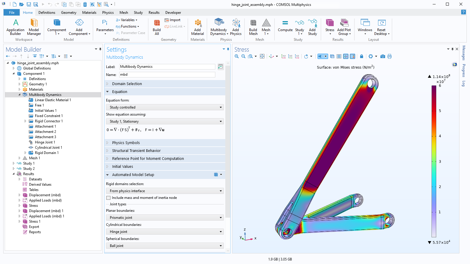
Rigid and Flexible Parts
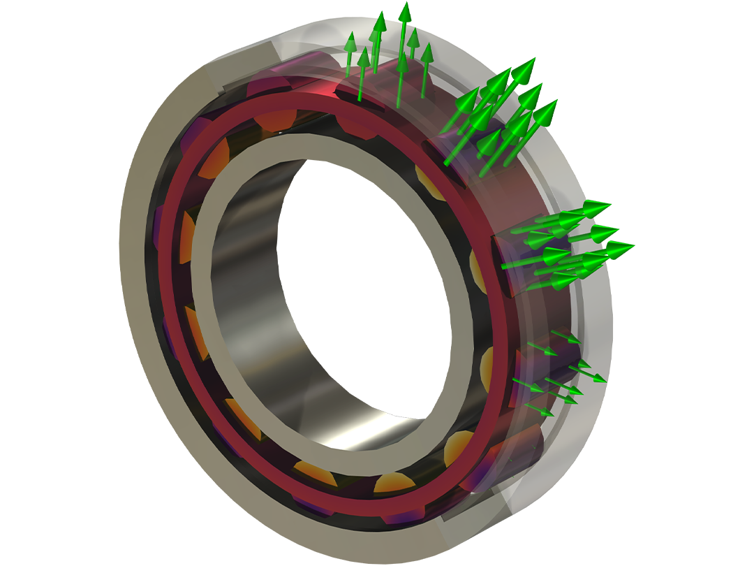
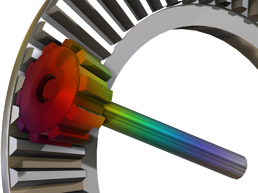
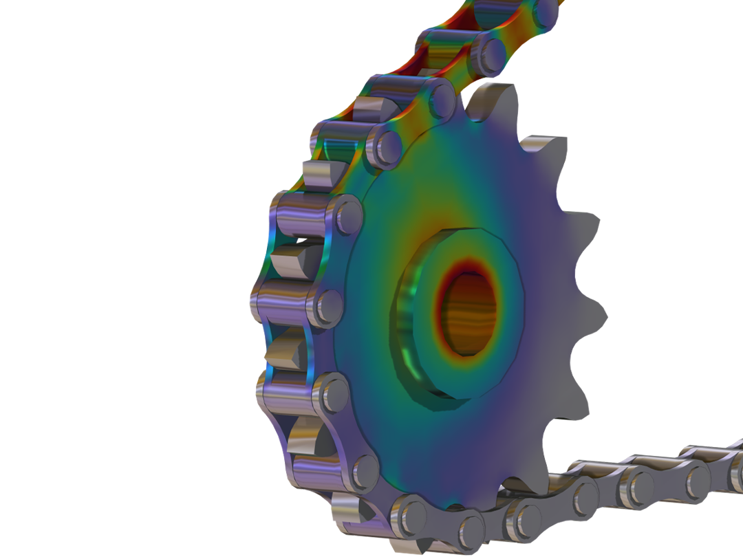
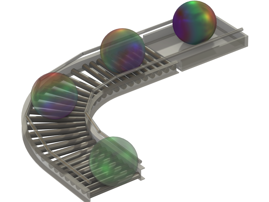
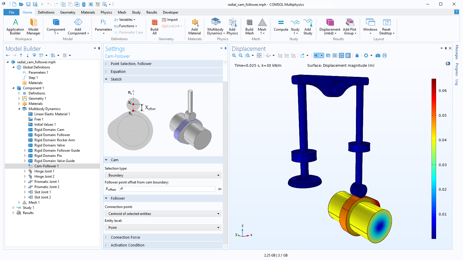
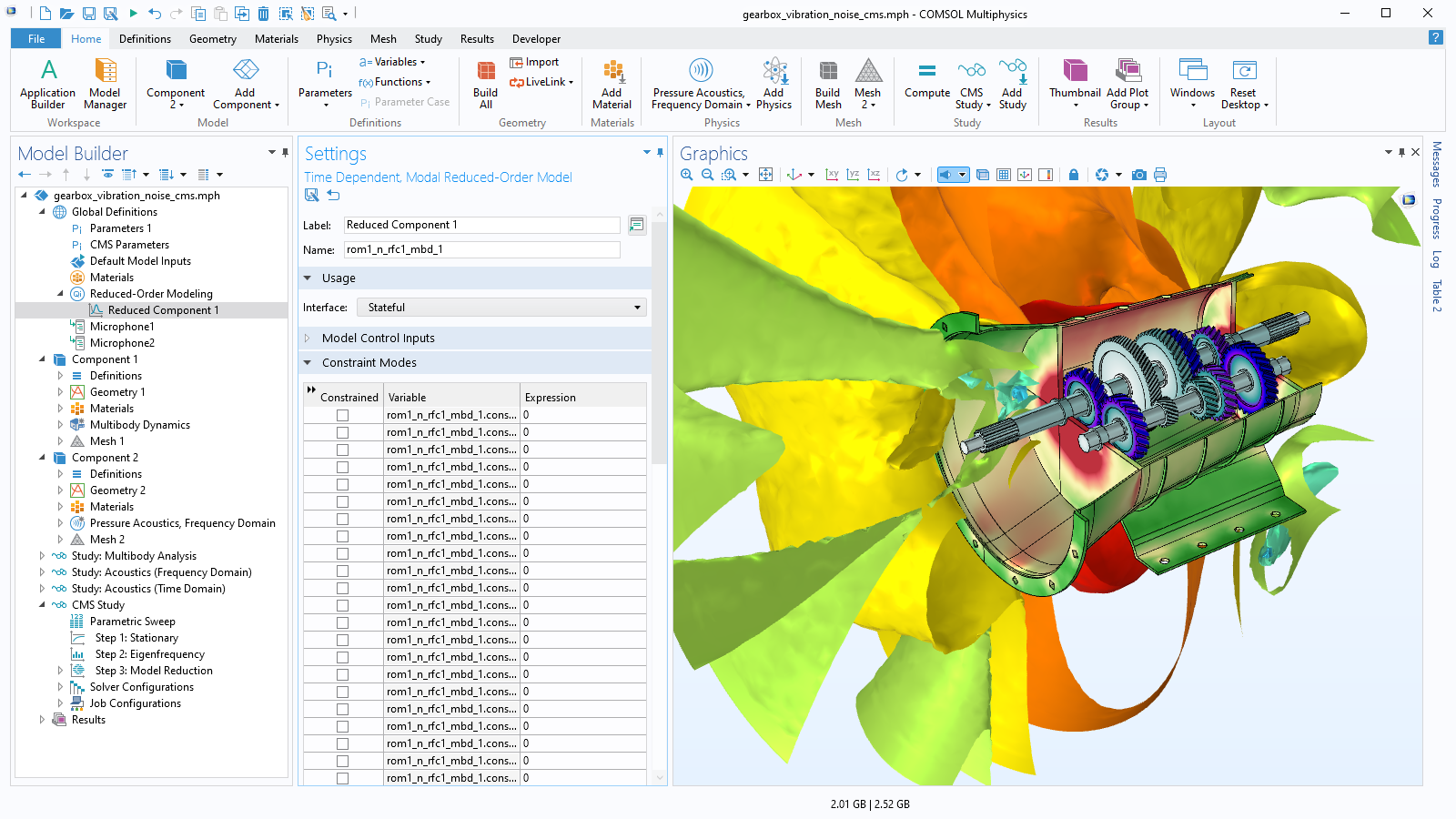
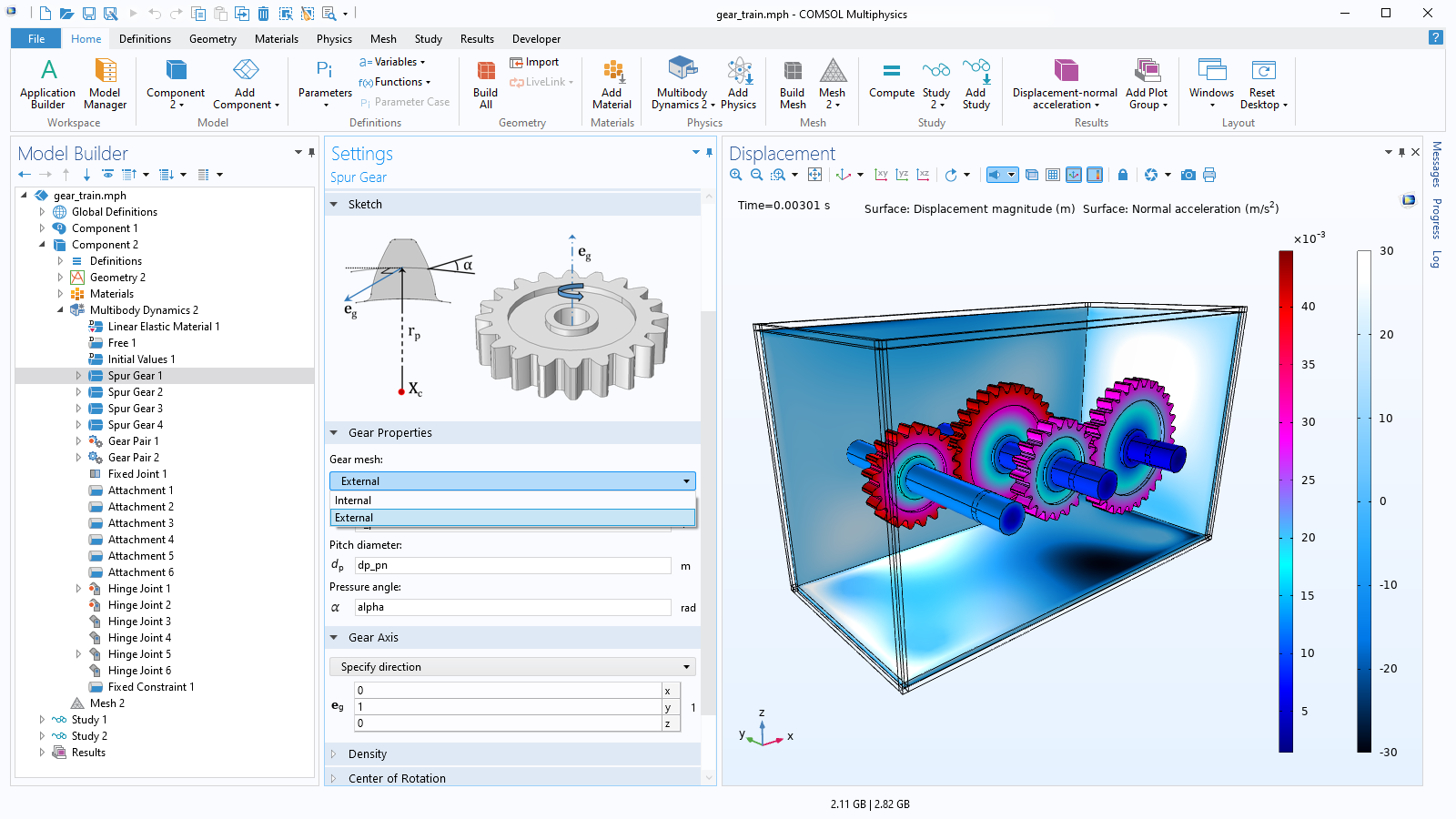
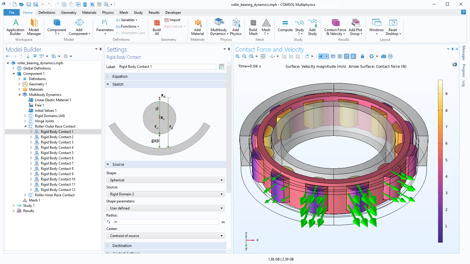
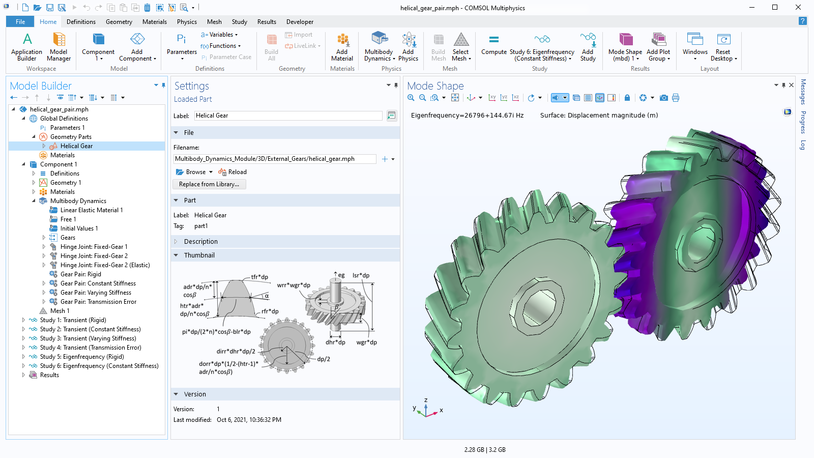
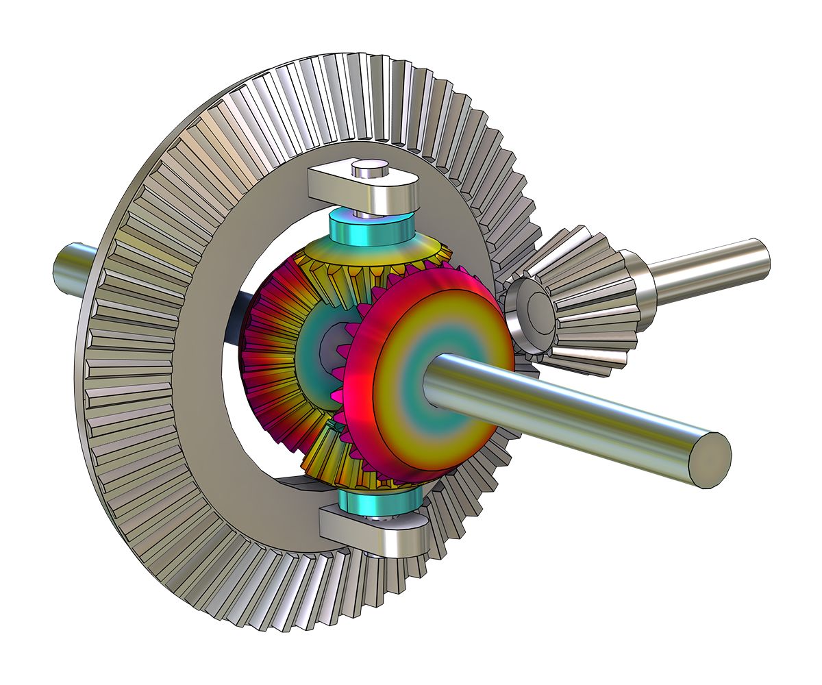
When modeling multibody systems, flexible and rigid bodies are connected using various types of joints, gears, cams, bearings, springs, or dampers and are subjected to large displacements and rotations. One of the advantages of using the Multibody Dynamics Module is how easy it is to mix rigid and flexible parts.
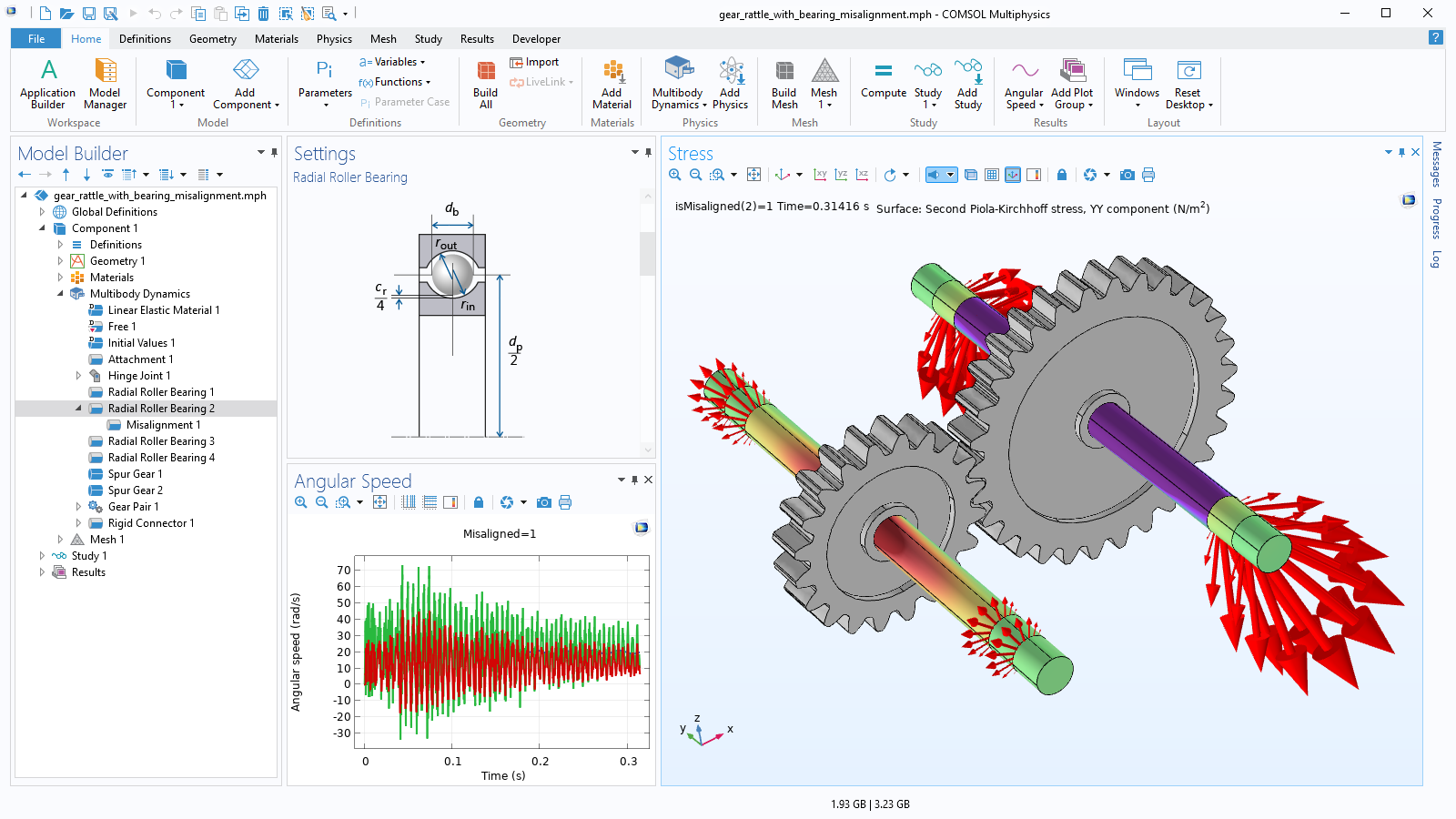
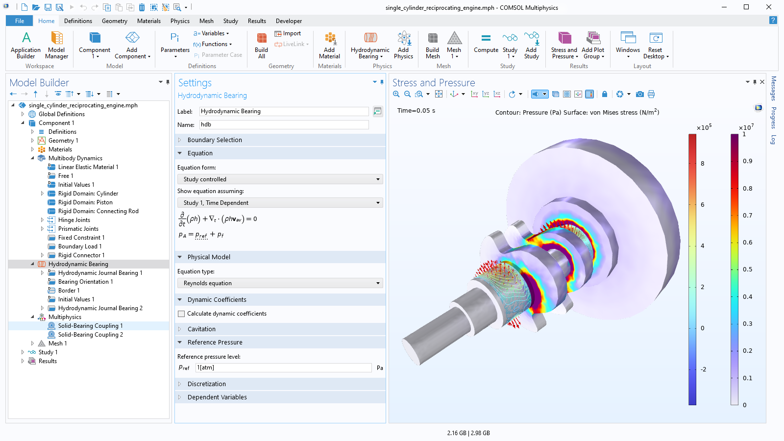
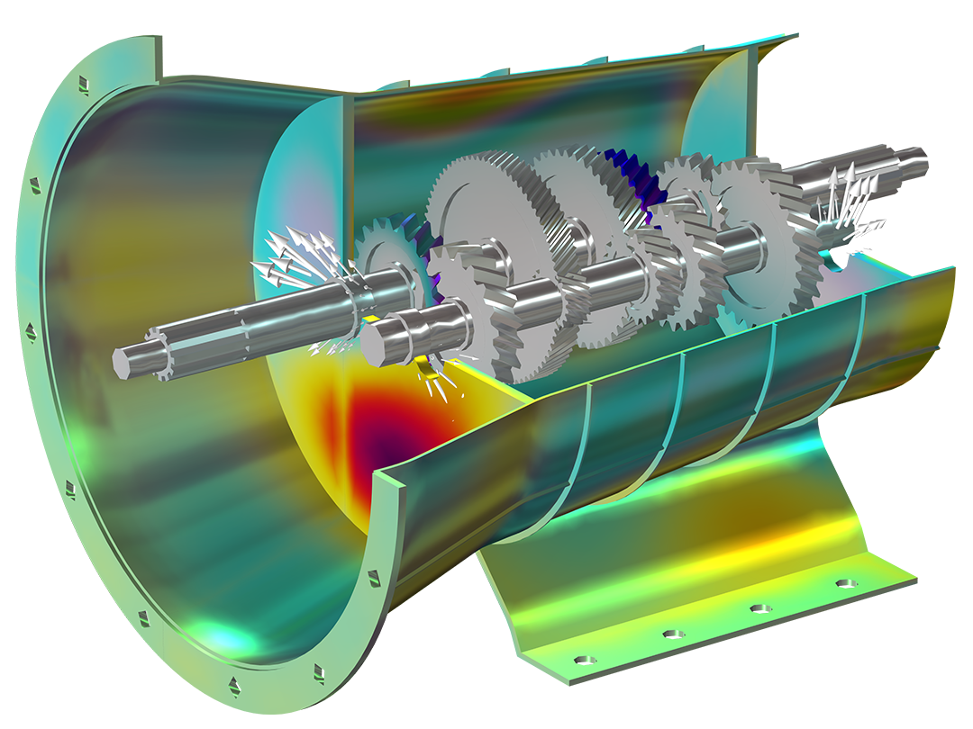
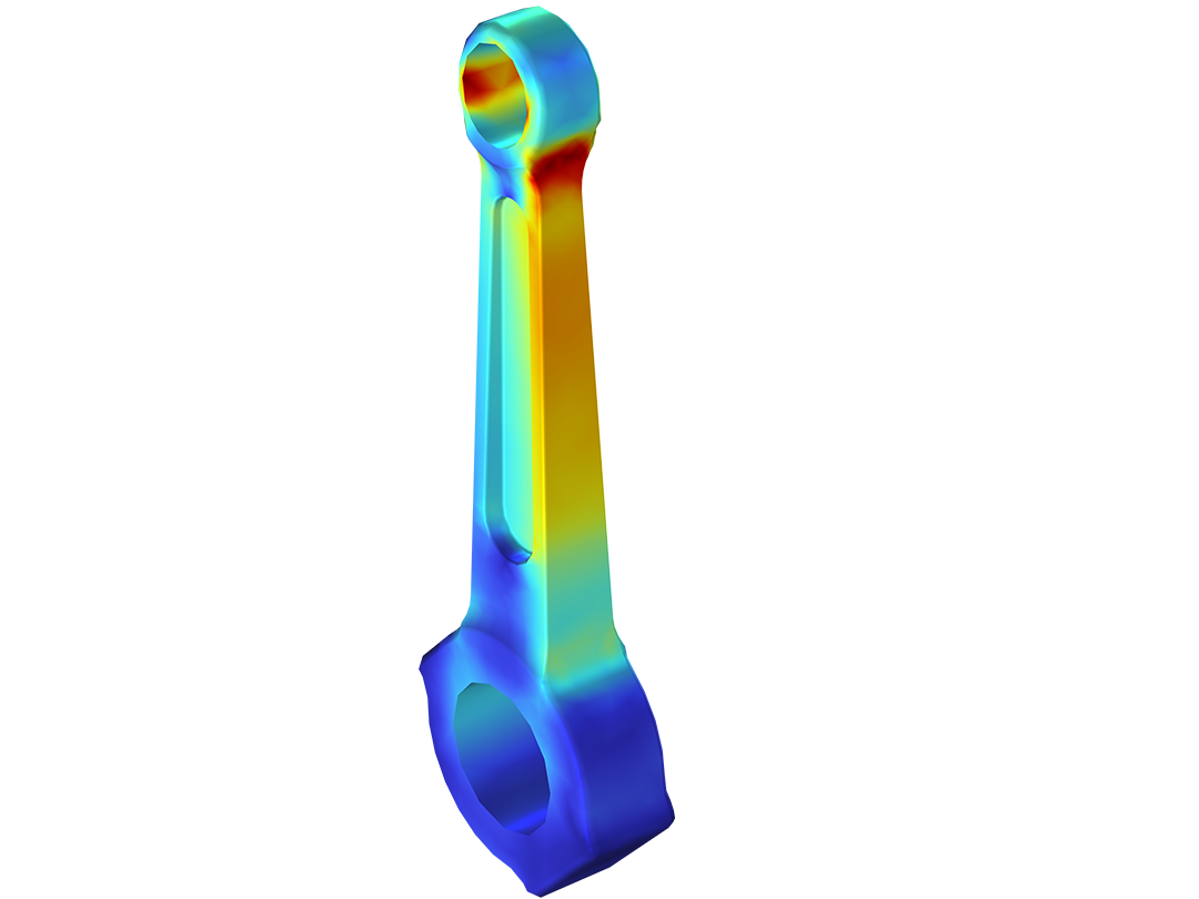
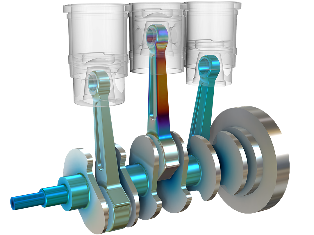
Generally, all or the majority of the parts in a multibody simulation are rigid and are thus represented by only the degrees of freedom of a rigid body. However, in some cases, it may be desirable to represent one or several parts as flexible. With the material models available within the module, it is possible to selectively assign rigid and flexible parts to a model for detailed structural analyses that include the effects of nonlinear materials. The Multibody Dynamics Module can be used, for example, to calculate forces experienced at the joints of the rigid parts of the structure as well as stresses generated in the flexible components.