
Electrocoating
Study the deposition of a highly resistive coating, which leads to a dynamic change in current distribution over coated areas.
Model and Control Electrodeposition Processes
The Electrodeposition Module, an add-on to COMSOL Multiphysics®, enables engineers and scientists to understand, optimize, and control electrodeposition processes using simulation. This is a cost-effective approach for investigating the influence of different parameters, including cell geometry, electrolyte composition, electrode reaction kinetics, operating voltages and currents, and temperature effects.
In the Electrodeposition Module, a typical simulation yields the current distribution at the surface of the electrodes as well as the thickness and composition of the deposited layer. You can model various applications, such as the fabrication of electrical and thermal conductors and the electroforming of parts with thin complex shapes. You can also combine the Electrodeposition Module with other modules in the COMSOL product suite to further expand its multiphysics capabilities and simulate, for example, turbulent and two-phase flow.
Contact COMSOL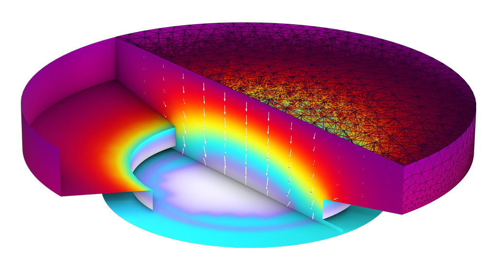
The Electrodeposition Module is well suited for a wide variety of applications.
Study the deposition of a highly resistive coating, which leads to a dynamic change in current distribution over coated areas.

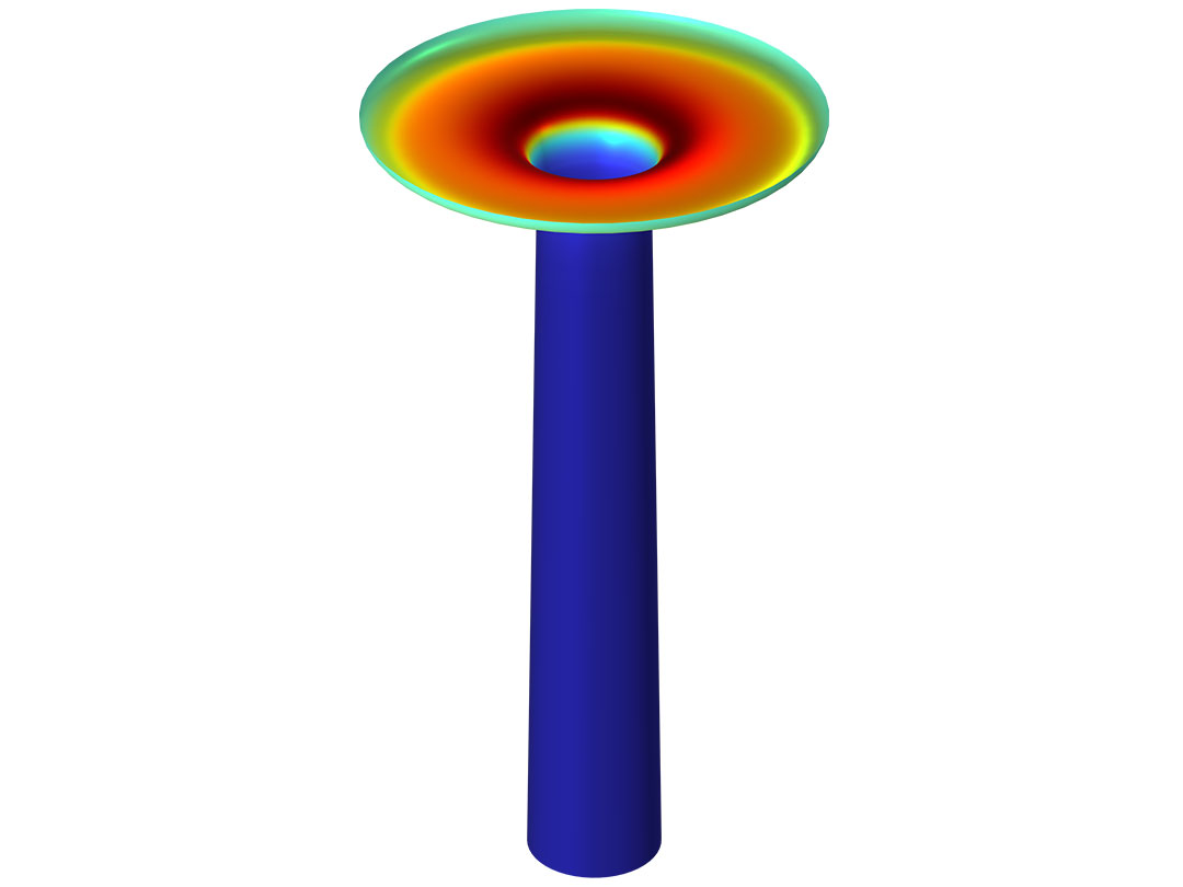
Investigate plating uniformity in multiple components.

Extract copper from an electrolyte solution and study the deposition rate at the cathode surface.
Investigate an electrochemical machining process and how the changing geometry impacts the progress of material removal.

Attenuate small protrusions during metal deposition by reverse pulse dissolution.

Simulate electrodeposition for PCB manufacturing.

Gain uniform protective or decorative coating on metals and plastics by simulating the anodization process and optimize the electrode coverage.

Model adsorption–desorption kinetics in narrow vias and trenches.
Discover the features for modeling different phenomena in electrodeposition cells.

COMSOL Multiphysics® and the Electrodeposition Module provide users with ready-made, user-friendly interfaces for modeling electrodeposition processes. The basic functionality is covered by the Primary Current Distribution, Secondary Current Distribution, and Tertiary Current Distribution interfaces. These make it possible to model current distribution as well as surface kinetics with polarization curves and to include mass transport effects and bulk equilibrium reactions in models.
By choosing one of these interfaces, the user can select the level of fidelity needed to obtain a sufficiently accurate description of the system in mind, whether the model needs to include only ohmic effects or is more complex, such as one that needs to include mass transport and equilibrium reactions for multiple species. COMSOL Multiphysics® makes it possible to seamlessly add as many species and reactions as needed for a given physical system.

The Electrodeposition Module includes an Electrode, Shell interface for modeling electric current conduction in the tangential direction on a boundary. The interface is suitable for modeling thin electrodes where the potential variation in the normal direction to the electrode is negligible. In this case, the thin electrode domain is replaced by a partial differential equation formulation on the boundary. With this replacement, the problem size can be reduced and potential problems with mesh anisotropy in the thin layer can be avoided.

The Electrodeposition Module enables modeling of electrochemical charge transfer reactions where the kinetics expressions can be arbitrary functions of the modeled variables. This includes, for example, chemical species concentration, local electrode and electrolyte potential at the electrode–electrolyte interface, and temperature.
In the Secondary Current Distribution interface and Tertiary Current Distribution interface, parameters can be entered for the electrode kinetics, such as exchange current density, anodic and cathodic charge transfer coefficients, stoichiometry, and equilibrium potential for the electrode reactions in your system. Competing reactions can also be added on a single electrode surface, such as hydrogen evolution at the plating electrode. In addition, under the Chemical Species Transport branch, the Chemistry interface is available for defining various homogeneous and heterogeneous reactions.

The Electrodeposition Module can be combined with other add-on products in the COMSOL product suite. This enables the user to couple the physics that describe an electrodeposition or etching process with other modules, for example, with the Heat Transfer Module to study thermal effects or with the CFD Module to understand the effects of swirl, turbulent, or two-phase flow.

When deposited metal layers or anode thickness variations are small, the module is able to keep track of the plated layer thickness and how this may influence ohmic effects in the electrode, without actually changing the geometry. A variable for the thickness is introduced that also affects the local electrical conductance of the electrode. The changes in the thickness of the electrode can be automatically calculated from the electrode kinetic expressions by defining the stoichiometry coefficients, the molar mass, and the density of the deposited or consumed metal for the electrode reactions.

The Electrodeposition Module contains predefined multiphysics interfaces for the time-dependent modeling of deformations that occur as a result of deposition or dissolution processes in electrochemical cells. Such modeling involves using a deforming geometry where the velocities of the boundaries are prescribed by the electrochemical reactions.
In addition, the Level Set interface and Phase Field interface are available for modeling electrodeposition where the topology of the electrode surface changes as a result of the electrodeposition processes.

The Electrodeposition Module can be used to model the transport of chemical species through diffusion, convection, and migration in dilute solutions. The Transport of Diluted Species in Porous Media interface is used for computing the species concentration as well as the transport in free and porous media. This can be used in cases where either the solid-phase substrate is exclusively immobile or where a gas-filling medium is also assumed to be immobile.
A Nernst-Planck Equations interface is available for computing concentrations in electrolytes subjected to electric fields. It is also available for modeling generic electrochemical cells with significant concentration gradients of the current-carrying species (ions). Additionally, the Surface Reactions interface can be used to model Fickian transport of surface species.

In electrochemical cells, irreversible voltage losses can occur because of charge transport in the electrolyte or solid conductor materials, activation overpotentials in the electrode reactions, and heat of mixing. In addition, reversible heat sources and sinks can appear due to the entropy changes in the electrode reactions.
The Electrochemical Heating multiphysics coupling is available for defining heat sources based on the sum of irreversible heat (Joule heating and activation losses) and reversible heat effects in an electrochemistry interface. You can also use the heat source variables defined by the electrochemistry interfaces when setting up manual couplings between different components in a model.
Every business and every simulation need is different.
In order to fully evaluate whether or not the COMSOL Multiphysics® software will meet your requirements, you need to contact us. By talking to one of our sales representatives, you will get personalized recommendations and fully documented examples to help you get the most out of your evaluation and guide you to choose the best license option to suit your needs.
Just click on the "Contact COMSOL" button, fill in your contact details and any specific comments or questions, and submit. You will receive a response from a sales representative within one business day.
Request a Software Demonstration