Synchronize CAD Geometries in Solid Edge® and COMSOL Multiphysics®
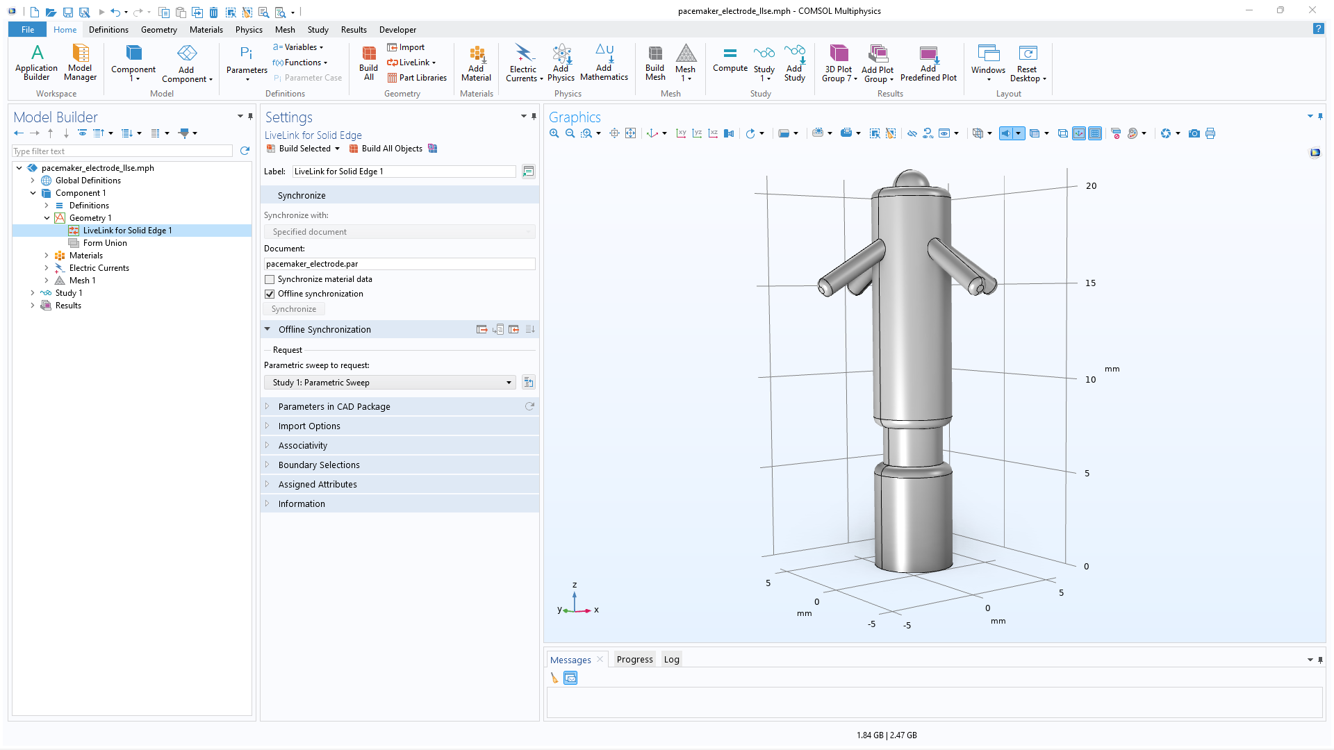
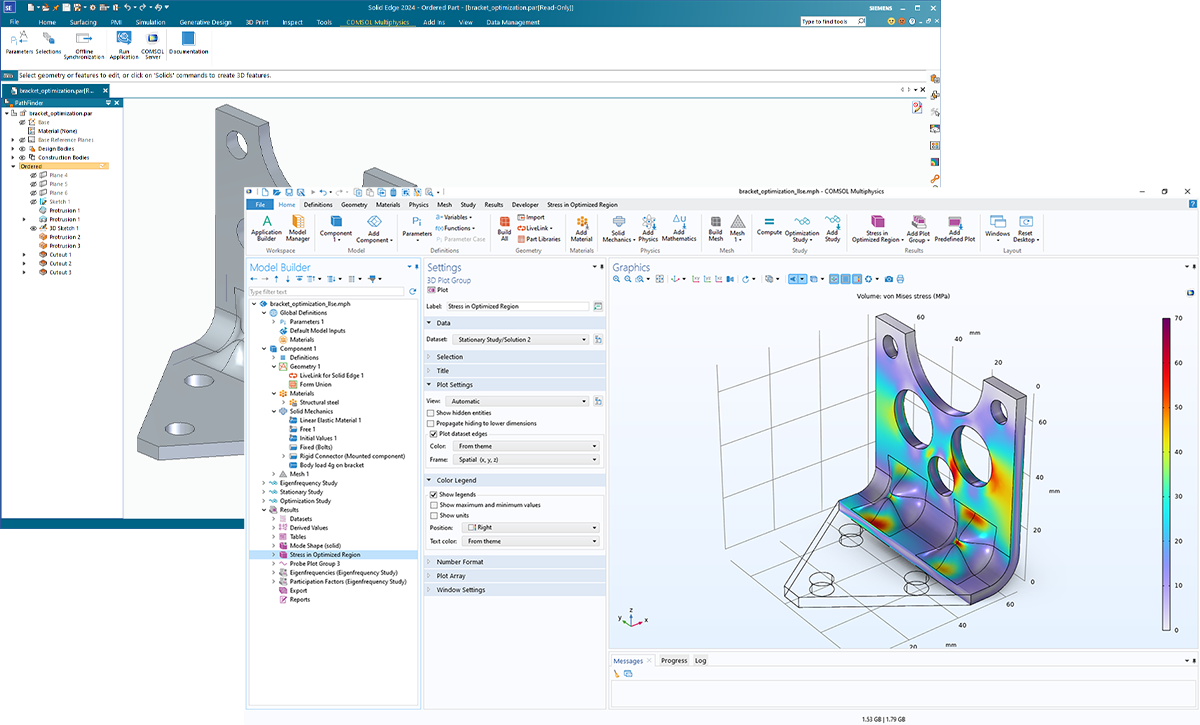
LiveLink™ for Solid Edge® enables synchronization between a COMSOL model's geometry and the corresponding Solid Edge® CAD file. LiveLink™ for Solid Edge® ensures that any design changes are automatically updated, eliminating the need for manual import and export each time changes are made. During the geometry synchronization process between the two programs, material and physics definitions as well as boundary conditions remain associated with their respective CAD entities, even through design alterations. LiveLink™ for Solid Edge® also keeps track of the synchronized file’s name and path to prevent synchronizing an incorrect document.
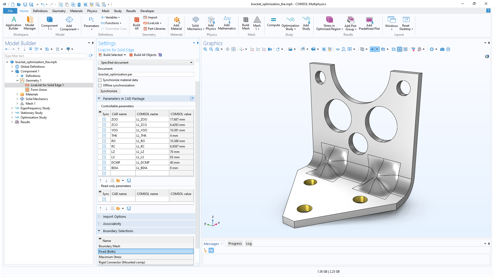
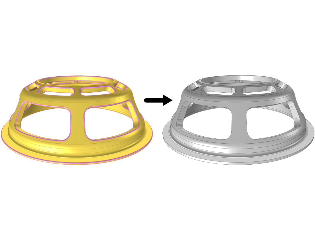
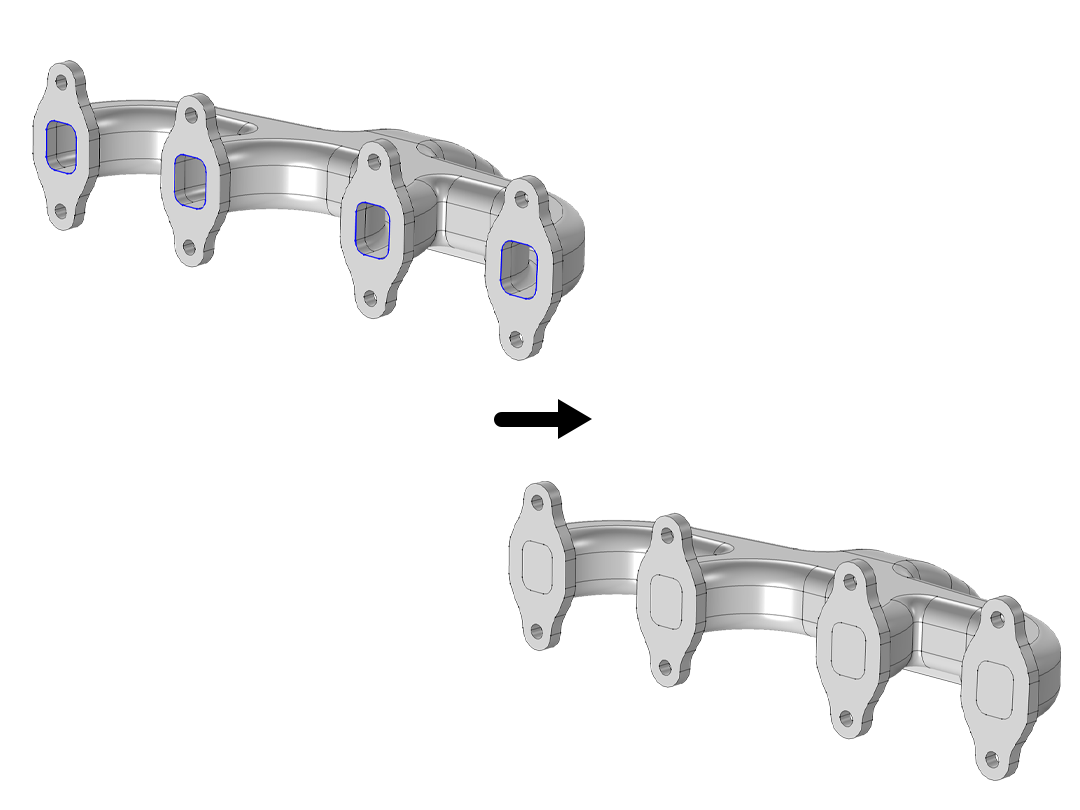
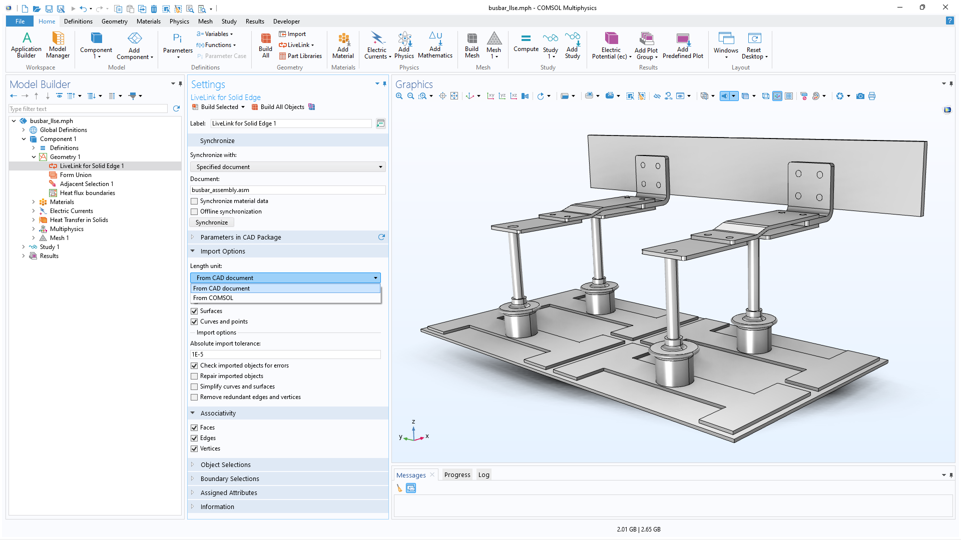
The LiveLink™ for Solid Edge® functionality includes several options for importing a geometry into COMSOL Multiphysics® from Solid Edge®. The length unit can be taken from the CAD document (the default option) or COMSOL®. The objects that are imported from Solid Edge® will include solids, surfaces, curves, and points, but any of these can be excluded if it is not applicable to the simulation.