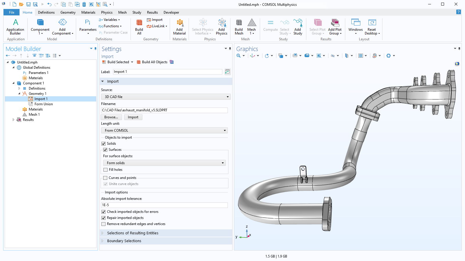
CAD Import Module

Import CAD Files into COMSOL Multiphysics® and Prepare Them for Analysis

The CAD Import Module add-on to the COMSOL Multiphysics® simulation software assists the modeling workflow in two primary ways. First, it makes it possible to import geometries from a variety of third-party CAD file formats into the software, including Parasolid® and ACIS®, standard formats such as STEP and IGES, and native file formats from various CAD systems. Second, the module helps ensure that the imported geometry is ready for analysis by providing tools for repairing errors introduced during transfer, defeaturing overly detailed geometry, and removing geometric entities that would otherwise result in unnecessarily fine meshes.

Contact COMSOL
The CAD geometry of a gas turbine model.

Importing CAD Files

Most CAD software support exporting to the Parasolid®, ACIS®, STEP, and IGES file formats, all of which can be readily imported into COMSOL Multiphysics® using the CAD Import Module. In addition, there is support for importing native file formats from several CAD systems, including SOLIDWORKS®, Inventor®, PTC Creo Parametric™, NX™, and AutoCAD®. Support for importing the native file format of CATIA® V5 is provided through the separate File Import for CATIA® V5 add-on. When the CAD Import Module is installed, all imported CAD models are automatically converted into a Parasolid® geometry using the Parasolid® geometry engine included with the module.

These geometries can subsequently be modified within COMSOL Multiphysics® using the CAD Import Module. In addition to fixing errors, users can make other adjustments, such as creating a surrounding CFD, acoustics, or electromagnetics domain. (Most CAD models represent the object to be manufactured, whereas simulations often focus on the physical phenomena around that object, such as airflow.) Once the modifications are complete, the CAD Import Module can export the updated geometry in IGES, STEP, Parasolid®, or ACIS® formats for use in other tools.

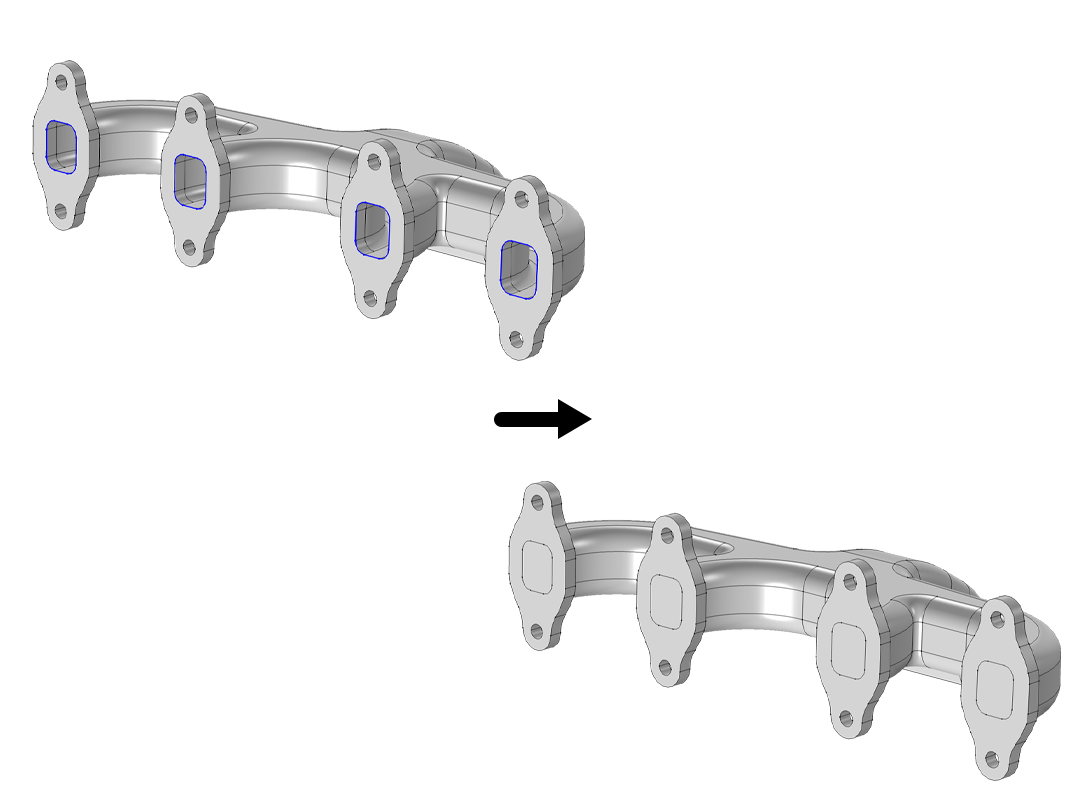
The import functionality supports associative geometry import, allowing physics settings and other selections to be retained on the geometry. When a file is imported, COMSOL Multiphysics® reads the information in the CAD file to identify its geometric entities. If the file is later reimported due to a design change, all selections in COMSOL Multiphysics® are automatically updated and preserved based on associativity rules, reducing the need to repeat setup work. This associative information is typically available when importing CAD files saved in the native format of the software where it was created.

Supported Formats for File Import and Export

Note that not all file formats are supported on all operating systems; for details, see the system requirements. The STL, PLY, 3MF surface mesh formats are supported by COMSOL Multiphysics® without add-on products.

File Format Extension Version Import Export
ACIS® .sat, .sab, .asat, .asab

Up to 2025 1.0 (import),
R4, R7, 2016 1.0 (export)

AutoCAD® .dwg 2.5–2025
AutoCAD® DXF™ .dxf 2.5–2025
IGES .igs, .iges Up to 5.3
Inventor® assemblies .iam 11–2025
Inventor® parts .ipt 6–2025
NX™ .prt Up to 2406
Parasolid® .x_t, .xmt_txt, .x_b, .xmt_bin Up to V37.0
PTC Creo Parametric™ .prt, .asm 1.0–11.0
PTC Pro/ENGINEER® .prt, .asm 16 to Wildfire® 5.0
SOLIDWORKS® .sldprt, .sldasm 98–2025
STEP .step AP203, AP214, AP242 (import),
AP203 (export)

Repair a Geometry on Import

The purpose of building a CAD model is to produce a digital representation of a real product. This digital model would include 3D geometry along with the information needed for manufacturing. While a 3D CAD geometry typically reflects the real object accurately, small and often unnoticeable anomalies can be present. These may be due to numerical limitations in representing complex shapes, limitations of older CAD file formats, human error, or issues that occur during data translation between formats. Such anomalies can result in faces that do not align perfectly at edges or inconsistencies in face normals and edge directions. These issues can interfere with creating valid, watertight geometry that can be meshed in COMSOL Multiphysics®. To address this, geometry repair is performed automatically during the import process, assisting in the initial setup of simulations.

In addition to the automatic repair performed during import, the CAD Import Module also provides tools for manual repair of CAD models. For example, faces can be manually selected and knitted together to form a solid, using a specified tolerance to close any gaps. Alternatively, the edges of gaps can be automatically detected, and these edges can be used to generate a new face that covers the gap and completes the solid.


Automatic Geometry Cleanup

Even after a CAD model has been properly repaired, it may still be challenging to use in a simulation due to geometric complexity and the presence of many small features. If not removed before meshing, these features can lead to an excessive number of mesh elements, increasing computational demands more than necessary.

To simplify the geometry and reduce the simulation size, small features such as slivers, short edges, narrow gaps, and thin domains are automatically identified and removed in preparation for analysis. The cleanup process is transparent and includes editable steps. An optional wizard can be used to adjust the detail size tolerance and select which cleanup operations to apply.

Depending on the type and complexity of the features, the automatic cleanup can apply different methods, including virtual geometry operations, tools from the CAD Import Module or Design Module, and, in some cases, switching to a mesh-based representation of the geometry.

Defeature a Geometry for Analysis

While certain design features, such as fillets, grooves, threads, and holes, are necessary for manufacturing, they may not be relevant for a particular type of simulation. The CAD Import Module provides tools for removing these features and simplifying the geometry. There is functionality for deleting fillets and chamfers, filling holes, and removing groups of faces by replacing them with a uniform surface using filling or patching operations.

Additional unwanted features may result from the CAD modeling or import process itself, such as small faces, sliver faces, spikes, and short edges. While these unintentional features are typically detected and removed by the automatic geometry cleanup, a tolerance value can be specified in a dedicated interface to identify and remove all or selected instances of unintentional features. Defeaturing can also be performed automatically during import using the same tolerance settings applied for geometry repair. The resulting simplified geometry can then be exported to CAD file formats for sharing with others.

While the defeaturing functionality makes the CAD Import Module well suited for preparing individual CAD parts, the small gaps and overlaps often found between components in a CAD assembly can be addressed using the advanced Boolean geometry operations available in the Design Module. For example, when performing a Boolean union on two objects separated by a small gap, the gap can be automatically closed by specifying a suitable tolerance.

Perform Virtual Geometry Operations to Simplify Mesh

One way the automatic geometry cleanup functionality removes small geometric features is through the use of virtual operations. Rather than modifying the actual geometry, virtual operations instruct the mesher to ignore features that have little or no impact on the simulation results. The mesh is then generated on a virtual version of the geometry. These operations can include ignoring vertices, edges, and faces; forming composite edges and faces; collapsing edges and faces; and more.

There are two ways to apply virtual geometry operations: Faces, edges, and vertices can be manually selected to be ignored, or the Remove Details operation can be implemented, which automatically identifies and removes small features through a sequence of virtual operations. These operations can then be reviewed and edited as needed.

These operations are included in the COMSOL Multiphysics® platform and are a great complement to the defeaturing features in the CAD Import Module. This functionality is particularly useful when the features of the geometry cannot be easily removed through defeaturing or repair, or when the simulation requires that the curvature of the geometry is kept intact.

Interfacing Directly with CAD Software

For CAE engineers who also uses CAD software, COMSOL provides several add-on products that connect COMSOL Multiphysics® to each of the major CAD software packages, using specialized LiveLink™ technology. The synchronization feature in the LiveLink™ products automatically updates the geometry in one program when changes are made in the other. This feature eliminates the need to continuously export and import the entire CAD geometry when changes are needed for further analysis.

The following products contain this functionality:

Every business and every simulation need is different.

In order to fully evaluate whether or not the COMSOL Multiphysics® software will meet your requirements, you need to contact us. By talking to one of our sales representatives, you will get personalized recommendations and fully documented examples to help you get the most out of your evaluation and guide you to choose the best license option to suit your needs.

Just click on the "Contact COMSOL" button, fill in your contact details and any specific comments or questions, and submit. You will receive a response from a sales representative within one business day.

Next Step

Request a Software Demonstration